
Low-sidelobe circular polarized microstrip array antenna applied to electronic toll collection system

An electronic non-parking and charging system technology, applied in the field of low-side lobe right-handed circularly polarized microstrip array antennas, can solve the problem of simultaneous antenna satisfaction, achieve high gain, low axial ratio, and reduce side lobe levels

Inactive Publication Date: 2012-03-28
BEIHANG UNIV
View PDF4 Cites 11 Cited by
  • Summary
  • Abstract
  • Description
  • Claims
  • Application Information

AI Technical Summary

Problems solved by technology

However, existing antennas cannot satisfy these requirements well at the same time.

Method used


Image

  • Low-sidelobe circular polarized microstrip array antenna applied to electronic toll collection system
  • Low-sidelobe circular polarized microstrip array antenna applied to electronic toll collection system
  • Low-sidelobe circular polarized microstrip array antenna applied to electronic toll collection system

Examples


Embodiment Construction

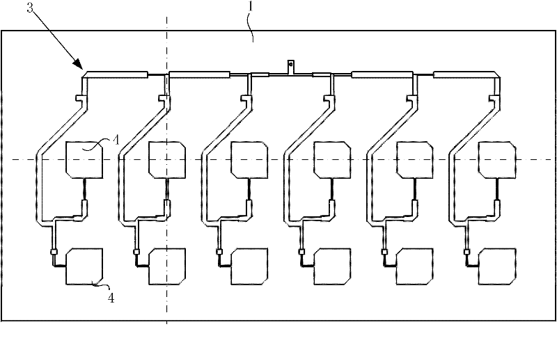
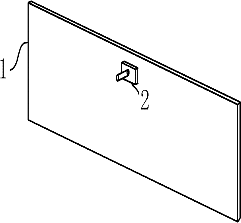
[0029] The invention is a low-side lobe circularly polarized microstrip array antenna for an electronic non-stop charging system, such as figure 1 , figure 2 As shown, it includes a microstrip antenna board 1 and a feed connector 2 . The microstrip antenna board 1 is composed of two layers of metal foil 101 and a layer of dielectric substrate 102, such as image 3 As shown, a dielectric substrate 102 is arranged between two layers of metal foils 101, and the three are fixed to each other. The dielectric substrate 102 is polytetrafluoroethylene glass cloth. Compared with ceramic plates and epoxy plates, polytetrafluoroethylene glass cloth has a smaller dielectric constant (2.1-3.5) and a smaller loss angle (tanδ≤3× 10 -3 ), moderate hardness and less loss. In order to reduce the loss as much as possible and improve the antenna gain, the dielectric constant of the dielectric substrate 102 selected by the present invention is 2.65, and the loss angle tanδ≤7×10 -4 , a thickn...


PUM


Abstract

The invention discloses a low-sidelobe circular polarized microstrip array antenna applied to an electronic toll collection (ETC) system, wherein the antenna is has a three-layer structure successively including a metal foil, a dielectric substrate and a metal foil. A microstrip feed network and radiation units are arranged on the metal foil on the top of the structure; the radiation units employs a grouping mode in which n radiation units are arranged transversely and two radiation units are arranged longitudinally. There is a rotation angle difference of 90 degrees anticlockwise between each of the radiation unit above the longitudinal column and each of the radiation unit below the longitudinal column; compared with a feed phase of the radiation unit below the longitudinal column, a feed phase of the radiation unit above the longitudinal column is delayed by 90 degrees; and magnitudes of the feed currents of the radiation units at the same longitudinal column are equal. A feed joint is utilized to realize application of current excitation on a whole microstrip feed network, so that the whole microstrip feed network applies currents on all the radiation units. A simplified dolph-chebyshev distribution is utilized for current magnitude ratios that are needed by the radiation units on a same transverse line; and current phases are equal. According to the invention, the microstrip antenna has advantages of low axial ratio, low sidelobe and high gain; and moreover, the antenna is easy to process and install; therefore, the provided antenna can be widely applied to the electric toll field and other related fields.

Description

technical field [0001] The invention belongs to the field of non-contact toll collection systems, in particular, it is a low-side-lobe right-hand drive for a road-side unit (RSU, Road-Side Unit) in an electronic toll collection system (ETC, Electronic Toll Collection). Circularly polarized microstrip array antenna. Background technique [0002] The electronic non-stop toll collection system uses Automatic Vehicle Identification (AVI for short) technology to complete the wireless data communication between the vehicle and the toll station, to carry out automatic vehicle identification and the exchange of relevant toll data, and to process the toll data through the computer network to realize Fully electronic toll collection system with automatic toll collection without parking. [0003] The electronic toll collection system works mainly through the non-contact communication between the RSU and the on-board unit (OBU, On-Board Unit). When using ETC, the owner only needs to i...

Claims


Application Information

Patent Timeline
Patent Type & Authority Applications(China)
IPC IPC(8): H01Q1/38H01Q13/08H01Q21/00
Inventor 白明邵一鹏
Owner BEIHANG UNIV
Learn More