Ku-frequency-band transmitting-receiving linear and circular polarization multiplexing feed source network

A technology of shared transceiver and circular polarization, applied to antennas, electrical components, etc., can solve the problems of difficulty in realizing the air tightness of the feed network, affecting the working bandwidth of the feed network, and large workload of debugging the feed network. Air tightness requirements, easy phasing, simple structure effect

Active Publication Date: 2016-10-12
NO 54 INST OF CHINA ELECTRONICS SCI & TECH GRP
View PDF4 Cites 4 Cited by
  • Summary
  • Abstract
  • Description
  • Claims
  • Application Information

AI Technical Summary

Problems solved by technology

The feed network with the above-mentioned structure is simple in principle and relatively mature in technology, but the narrow bandwidth of the waveguide sub-wave head directly affects the working bandwidth of the feed network, and the whole feed network has a large debugging workload, which is not suitable for mass production. Production
At the same time, due to the use of a DC motor to drive the waveguide phase shifter to switch between linear polarization and circular polarization, the mechanical structure is complex, the switching time is long, the switching rate is low, and the reliability is poor
The most important problem is that due to the impact of the circular waveguide rotary joint, it is difficult to achieve the airtightness of the entire feed source network. Airtightness throughout the life cycle, and maintenance work such as replacing oil seals is difficult

Method used


Image

  • Ku-frequency-band transmitting-receiving linear and circular polarization multiplexing feed source network
  • Ku-frequency-band transmitting-receiving linear and circular polarization multiplexing feed source network
  • Ku-frequency-band transmitting-receiving linear and circular polarization multiplexing feed source network

Examples


Embodiment Construction

[0041] Below in conjunction with accompanying drawing and specific implementation example the present invention will be described in further detail:

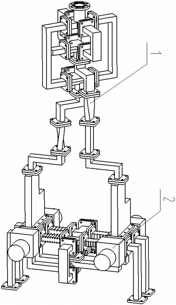
[0042] Such as figure 1 Shown is the structural diagram of the circular polarization multiplexing feed source network of the Ku frequency band transceiver common line of the present invention, the Ku frequency band transceiver common line circular polarization multiplexing feed source network of the present invention is composed of the Ku frequency band transceiver four-port network 1 and the Ku frequency band line circle The polarization switching network 2 is compounded.

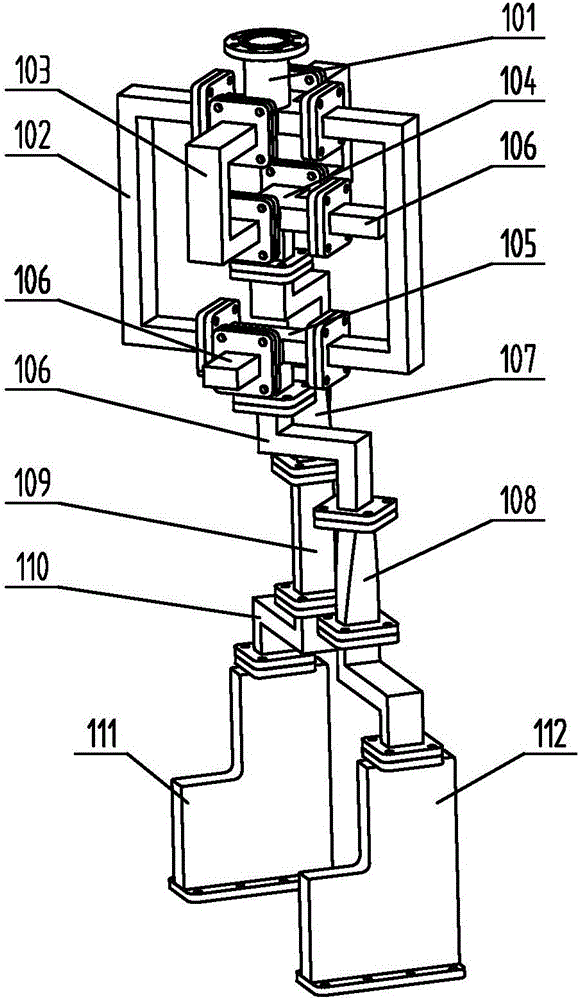
[0043] Such as figure 2 The four-port network 1 for transmitting and receiving in the Ku frequency band includes a door-twisting wave splitter 101, a first U-bend waveguide 102, a second U-bend waveguide 103, a first broadband magic T104, a second broadband magic T105, a waveguide load 106, -45° twisted waveguide 107, +45° twisted waveguide 108, phase com...


PUM


Abstract

The invention relates to a Ku-frequency-band transmitting-receiving linear and circular polarization multiplexing feed source network that is formed by combination of a Ku-frequency-band transmitting-receiving four-port network and a Ku-frequency-band linear and circular polarization switching network. The Ku-frequency-band transmitting-receiving four-port network consists of a door torsion type partial wave head, two U-shaped bending waveguides I, two U-shaped bending waveguides II, two broadband waveguide magic units T, two waveguide loads, two Z-shaped bending waveguides I, a +45-degree twisted waveguide, a -45-degree twisted waveguide, a phase compensation waveguide, two Z-shaped bending waveguides II and two transceiver frequency duplexers. Besides, the Ku-frequency-band linear and circular polarization switching network includes four waveguide switches, four E-plane bending waveguides, two U-shaped bending waveguides III, two U-shaped bending waveguides IV, two EH dual-plane bending waveguides, a receiving-frequency-band +/45-degree phase shifter, a transmitting-frequency-band +/- 45-degree phase shifter and two waveguide magic units T. According to the invention, the waveguide switches are used as linear and circular polarization switching components, so that switching is carried out rapidly and the in-place rate is high; and the airtightness of the feed source network is guaranteed. Meanwhile, the network has characteristics of compact structure, debugging avoidance, and excellent standing-wave, axial-ratio, and port isolation performances.

Description

technical field [0001] The invention relates to a circular polarization multiplexed feed source network of a Ku frequency band transceiver common line, in particular to two working states, which are respectively the Ku frequency band transceiver line polarization working state and the Ku frequency band transceiver circular polarization working state, belonging to reflective surface antennas Feed network field. Background technique [0002] In the satellite communication and measurement and control system, the reflector antenna is an indispensable and important part, and its performance directly determines the performance of the entire satellite communication and measurement and control system. As the core component of the reflector antenna, the feed network is used to realize the function of transmitting and receiving or polarization multiplexing of the reflector antenna. With the development of satellite communication and measurement and control technology, the system ofte...

Claims


Application Information

Patent Timeline
Patent Type & Authority Applications(China)
IPC IPC(8): H01Q15/24H01Q23/00
CPCH01Q15/24H01Q23/00
Inventor 詹英阮云国李振生张博曹国光邹火儿杜彪张文静
Owner NO 54 INST OF CHINA ELECTRONICS SCI & TECH GRP
Why Eureka
Try Eureka