Novel wideband multi-mode combined antenna

A combined antenna and broadband technology, applied to antennas, devices that enable antennas to work in different bands at the same time, and structural forms of radiation elements, can solve the problems of narrow frequency band and low gain of microstrip antennas

Inactive Publication Date: 2016-08-17
南京星腾通信技术有限公司
View PDF2 Cites 4 Cited by
  • Summary
  • Abstract
  • Description
  • Claims
  • Application Information

AI Technical Summary

Problems solved by technology

However, the microstrip antenna has the disadv

Method used


Image

  • Novel wideband multi-mode combined antenna
  • Novel wideband multi-mode combined antenna
  • Novel wideband multi-mode combined antenna

Examples


Embodiment 1

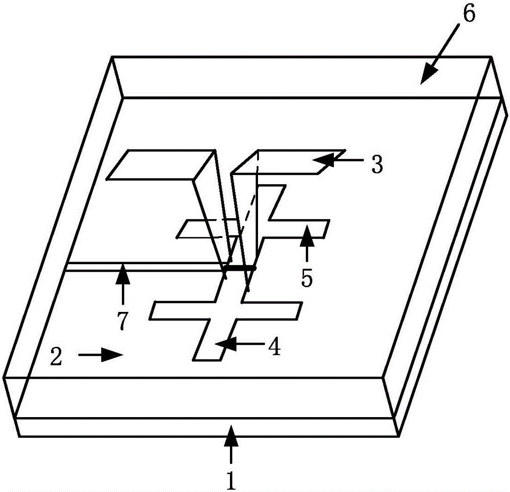
[0024] A new type of broadband multi-mode combined antenna, comprising a dielectric substrate 1 and a slot antenna 2 fixed on its upper layer, a dipole antenna 3 connected to both sides of the slot antenna 2, a metal frame 6 surrounding the dielectric substrate 1, and a pair of The slot antenna and the dipole antenna feed the coaxial line 7 .

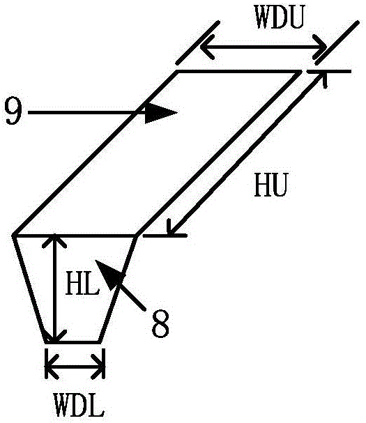
[0025] The upper side of the dielectric substrate 1 is covered with a metal layer, and the center of the metal layer has a long rectangular slit 4 and two short rectangular slits 5 that are symmetrical to each other and are perpendicular to the long central slit 4 of the metal layer; A dipole antenna 3 is connected to the center of the long slot 4, wherein the dipole antenna 3 is composed of a dipole antenna trapezoidal part 8 perpendicular to the dielectric substrate 1 and a dipole antenna rectangular part 9 parallel to the dielectric substrate 1. .

[0026] The length L of the long slot 4 is within the range of 1.5 times the waveleng...

Embodiment 2

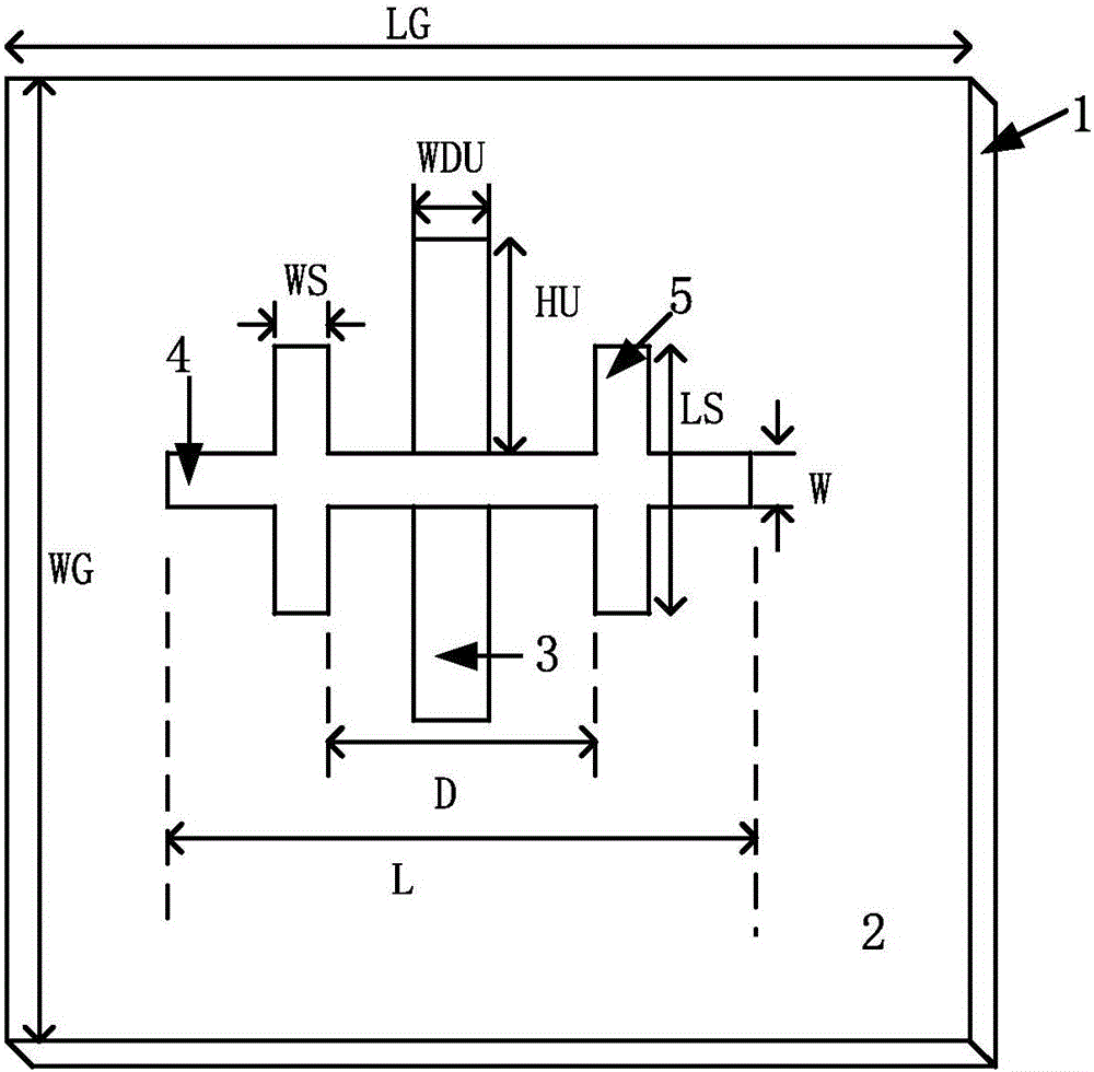
[0030] The broadband multimode combined antenna of the present invention combines figure 1 , figure 2 with image 3 , the dielectric constant of the dielectric substrate 1 is 2.65, the thickness is 1 millimeter, the length LG=200 millimeters and the width WG=200 millimeters; the range of the length L of the long slot 4 of the slot antenna 2 is about 1.5 times the wavelength of the center frequency 2.4GHz , width W=4 mm, the range of the long LS of the short slot is about 1 times the wavelength of the center frequency 2.4 GHz, the width WS=5 mm, and the distance D between the two symmetrical slots is about half the wavelength of the center frequency 2.4 GHz; The short side length WDL=4 millimeters of the vertical part of dipole 3, the long side length WDU=10 millimeters, high HL=40 millimeters, the length of the horizontal part is that HU is about the half-wavelength of center frequency 2.4GHz; The height of metal frame is 25 mm.

[0031] The reflection characteristics of t...


PUM

PropertyMeasurementUnit
Heightaaaaaaaaaa
Thicknessaaaaaaaaaa
Heightaaaaaaaaaa

Abstract

The invention relates to a wideband multi-mode combined antenna. The antenna comprises a dielectric substrate, a slot antenna, a folded dipole, a metal frame and a coaxial feed line, wherein the slot antenna is fixed at the upper side of the dielectric substrate, the dielectric constant of the substrate is 2.65, a rectangular gap is formed in the middle of the dielectric substrate, two short gaps are symmetrically formed in a direction perpendicular to the gap, the coaxial line is used for feeding at the middle of the gap, the folded dipole is vertically connected with the two sides of the middle of the gap, a perpendicular part of the dipole is a trapezoid, a horizontal part of the dipole is a rectangle, and the metal frame is vertically arranged at the periphery of the dielectric substrate. In a designed example, the bandwidth of the antenna is 1.9-2.83GHz, the relative bandwidth is 39.3%, two resonant points are generated at 2.10GHz and 2.69GHz, and wideband characteristic is achieved. The antenna confirms to the wideband requirement, can be applied to frequency bands of LTE, WCDMA, WLAN and RFID, is wide in application range, and has relatively high practicability.

Description

technical field [0001] The invention relates to an antenna, in particular to a novel broadband multi-mode combined antenna. Background technique [0002] Because of its small size, light weight, low price, low profile, easy to attach to the surface of metal objects, easy to integrate with active devices and microwave circuits into a unified component, and suitable for mass production, it has been favored by people in the past 30 years. extensive reliance. However, microstrip antennas have disadvantages such as narrow frequency band and low gain. [0003] In order to realize the requirement of broadband, the present invention proposes a new type of broadband multi-mode combined antenna, which effectively brings the two resonant frequencies close together, thereby broadening the bandwidth, covering LTE, WCDMA, WLAN and RFID frequency bands, and having a wide range of applications. Contents of the invention [0004] The invention mainly provides a novel broadband multi-mode...

Claims


Application Information

Patent Timeline
IPC IPC(8): H01Q1/38H01Q5/335
CPCH01Q1/38H01Q5/335
Inventor 程勇李亚丹吕文俊祝雷
Owner 南京星腾通信技术有限公司
Why Eureka
Try Eureka