Television cabinet assembly
A technology for TV cabinets and components, applied in the direction of cabinets, furniture parts, furniture accessories, etc., can solve the problems of high cost and inconvenience, and achieve the effect of improving continuous working performance and reliability
- Summary
- Abstract
- Description
- Claims
- Application Information
AI Technical Summary
Problems solved by technology
Method used
Image
Examples
Embodiment 1
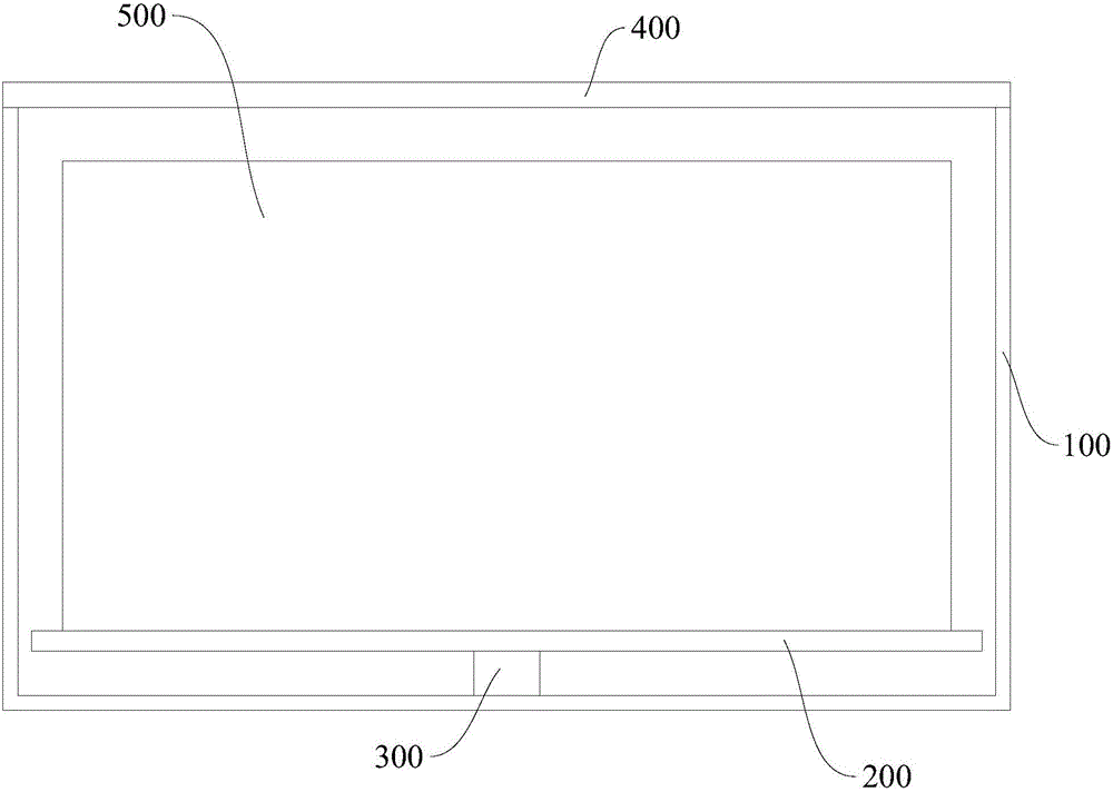
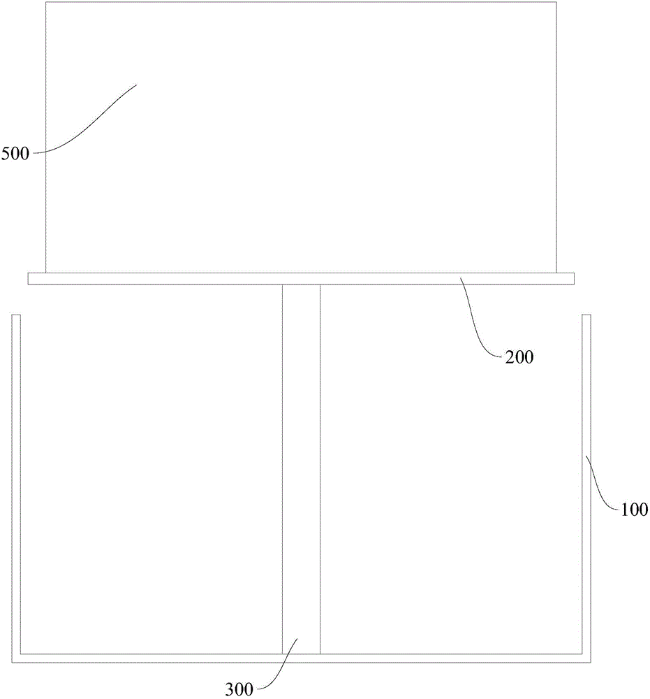
[0035] figure 1 It is a schematic diagram that the TV cabinet assembly in embodiment 1 is in a sinking position, figure 2 The schematic diagram of the TV cabinet assembly in the embodiment 1 in the rising position. In the figure, the meanings of each reference numeral are as follows: 100, cabinet body; 200, lifting platform; 300, lifting device; 400, cover plate; 500, TV set.
[0036] A TV cabinet assembly according to an embodiment of the present invention includes: a cabinet body 100 , a lifting platform 200 , and a lifting device 300 .
[0037]The lower end of the lifting device 300 such as a linear motor is connected to the inner bottom surface of the cabinet body 100, and the upper end of the lifting device 300 is connected to the lifting platform 200. sink position (eg figure 1 shown) and make the lifting platform 200 higher than the upper surface of the cabinet body 100 raised position (such as figure 2 shown) can be switched. The TV set 500 is placed on the lifti...
Embodiment 2
[0039] image 3 It is a structural schematic diagram of Embodiment 2 of the present invention; Figure 4 It is a structural schematic diagram of the circuit part in Embodiment 2 of the present invention; Figure 5 is a partial view of the self-adaptive air outlet in embodiment 2; Figure 6 It is a partial view of the element cooling fin in embodiment 2;
[0040] In the figure, the meanings of each reference mark are as follows: 1. Driver housing; 2. PCB circuit board; 11. Cleaning air intake device; 12. Filter device; 13. Cleaning pipeline; 14. Self-adaptive air outlet; 15 , bimetal sheet; 16, heat sink single body; 17, reflective mirror surface; 18, photosensitive switch; 19, circuit element; 20, air exhaust port; 23, insulating heat conductor;
[0041] The linear motor is electrically connected to the motor driver. The motor driver includes a driver housing and a PCB board arranged in the driver housing. Circuit elements are arranged on the PCB board.
[0042] The motor ...
Embodiment 3
[0063] Figure 7 It is a structural schematic diagram of the heat sink in Embodiment 3 of the present invention; in the figure, the meanings indicated by the reference signs that have appeared in the drawings used in Embodiment 2 follow the meanings in the drawings of Embodiment 2, and the newly appearing reference numerals The meanings expressed are as follows;
[0064] The difference between this embodiment and embodiment 2 is:
[0065] The individual heat sinks 16 are all arranged on an insulating and heat-conducting body 23 , and each individual heat sink 16 is divided along a circle.
[0066] The insulating heat conductor 23 can be an insulating layer attached to a metal material, so that each heat sink unit 16 is insulated from each other without significantly reducing the thermal conductivity, so that each heat sink unit 16 of the heat sink forms a capacitor.
PUM
 Abstract
Description
Claims
Application Information
 - R&D
- Intellectual Property
- Life Sciences
- Materials
- Tech Scout
- Unparalleled Data Quality
- Higher Quality Content
- 60% Fewer Hallucinations
Browse by: Latest US Patents, China's latest patents, Technical Efficacy Thesaurus, Application Domain, Technology Topic, Popular Technical Reports.
© 2025 PatSnap. All rights reserved.Legal|Privacy policy|Modern Slavery Act Transparency Statement|Sitemap|About US| Contact US: help@patsnap.com


