
Movable special-shaped pipe clamping device

A clamping device and special-shaped tube technology, which is applied to auxiliary devices, auxiliary welding equipment, welding/cutting auxiliary equipment, etc., can solve the problems of deviation error between workpiece and chuck, complicated adjustment and loading process, and reduced production efficiency. To achieve the effect of reducing offset error, convenient operation and improving production efficiency

Active Publication Date: 2016-08-24
HEBEI FLEXTRONICS ELECTRICAL TECH
View PDF7 Cites 10 Cited by
  • Summary
  • Abstract
  • Description
  • Claims
  • Application Information

AI Technical Summary

Problems solved by technology

[0004] The technical problem to be solved by the present invention is to solve the problem that the existing special-shaped pipe clamping device is in the form of a single adjustment roller in contact with the workpiece, which is prone to produce offset errors between the workpiece and the center of the chuck, and the process of adjusting the clamping is complicated. Time-consuming and labor-intensive, which reduces production efficiency

Method used


Image

  • Movable special-shaped pipe clamping device
  • Movable special-shaped pipe clamping device
  • Movable special-shaped pipe clamping device

Examples


Embodiment Construction

[0023] In order to make the purpose, technical solutions and advantages of the embodiments of the present invention clearer, the technical solutions in the embodiments of the present invention will be clearly and completely described below in conjunction with the drawings in the embodiments of the present invention. Obviously, the described embodiments It is a part of embodiments of the present invention, but not all embodiments. Based on the embodiments of the present invention, all other embodiments obtained by persons of ordinary skill in the art without making creative efforts belong to the protection scope of the present invention.

[0024] In the description of the present invention, it should be noted that unless otherwise specified and limited, the terms "installation", "connection" and "connection" should be understood in a broad sense, for example, it can be a fixed connection or a detachable connection. Connected, or integrally connected; it can be mechanically conn...


PUM


Abstract

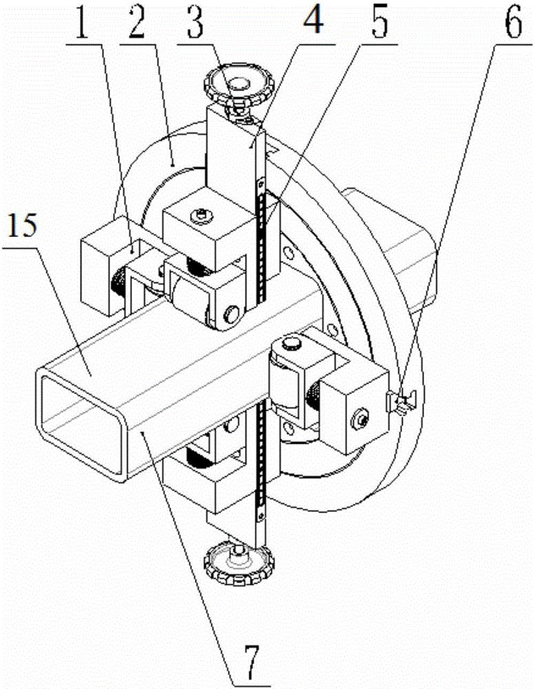
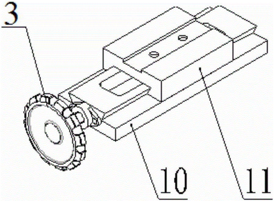
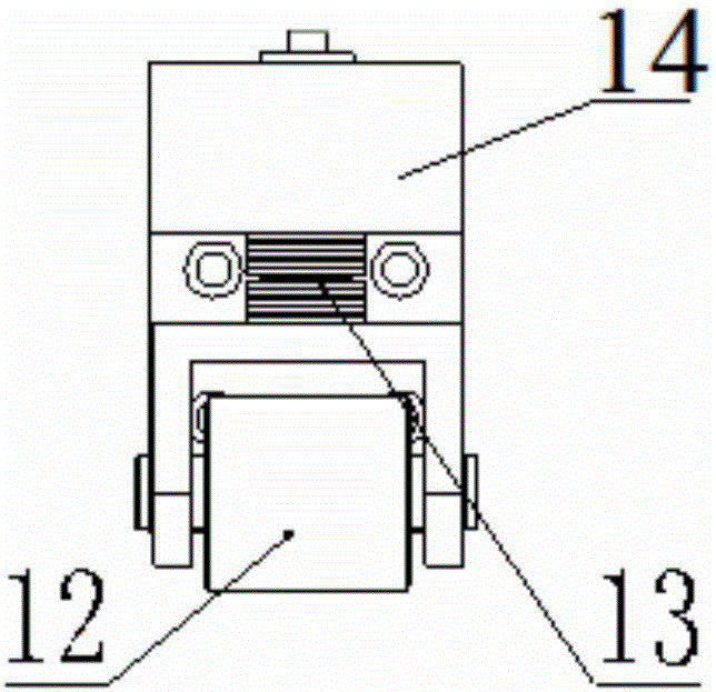
The invention relates to the technical field of cutting and welding, in particular to a movable special-shaped pipe clamping device. The movable special-shaped pipe clamping device comprises a four-claw chuck. Two sets of opposite base claws of the four-claw chuck are each provided with a roller assembly. The roller assemblies are in contact with the surface of a workpiece, so that the workpiece is clamped, and the workpiece can be adjusted to move in the axial direction of the four-claw chuck. One roller assembly is connected with the corresponding base claw through an adjusting sliding table, and the distance between the roller assembly connected with the adjusting sliding table and the surface of the workpiece can be adjusted through the adjusting sliding table. One of the two roller assemblies mounted on the four-claw chuck is arranged to be capable of being adjusted manually, and therefore the device can adapt to the surface shapes of more special-shaped pipes; the device firstly carries out locating through linkage of the four claws and the roller assemblies, it is guaranteed that the center of the workpiece is accurately aligned to the center of the four-claw chuck, then the workpiece is clamped and reinforced by manually adjusting part of the roller assemblies, and the deviation error of the center of the workpiece and the center of the four-claw chuck generated after clamping is reduced; and the process of adjusting and clamping is simple, and operation is convenient.

Description

technical field [0001] The invention relates to the technical field of cutting and welding, in particular to a movable special-shaped pipe clamping device. Background technique [0002] At present, the common clamping of special-shaped pipes is to install four manual adjustment slides on the turntable of the four-jaw chuck, and the front end of the slide is equipped with rollers, which is equivalent to the four-jaw manual adjustment rollers. When clamping the workpiece, each Adjust the roller to adjust the distance from the workpiece separately until the surface of the roller is in contact with the surface of the workpiece and pressed tightly, so this kind of clamping form is not easy to adjust the center like ordinary four-jaw single-action chuck clamping, and it is easy to cause workpiece and chuck Due to the offset error of the center, the process of adjusting the clamping requires repeated adjustments of each slide table and roller one by one, which is time-consuming and...

Claims


Application Information

Patent Timeline
Patent Type & Authority Applications(China)
IPC IPC(8): B23B31/10B23K37/04
CPCB23B31/101B23B31/102B23K37/0435
Inventor 李旭王利敏陈景斋
Owner HEBEI FLEXTRONICS ELECTRICAL TECH
Learn More