Pull rod locking device and clamping mechanism

A locking device and tie rod technology, which is applied in the field of injection molding and die-casting molding equipment, can solve the problems of large impact, easy damage of brake components, long processing cycle, etc., and achieve the effects of high strength, cost saving and efficiency improvement

Active Publication Date: 2016-08-24
BORCH MACHINERY
View PDF3 Cites 4 Cited by
  • Summary
  • Abstract
  • Description
  • Claims
  • Application Information

AI Technical Summary

Problems solved by technology

[0003] However, the locking and releasing of the traditional tie rods are realized by driving the two-half opening-closing structure of the brakes. Such multiple pull rods require multiple oil cylinders to drive, and synchronous actions cannot be realized, and the opening and closing of the brakes requires a mechanical limit. Large impact, high noise, and easy damage to brake components
In addition, a very small number of structures using a rotating brake require grooves on the pull rod to be used as a rotating avoidance position. This structure will not only result in low strength of the pull rod, but also difficult processing, long processing cycle and high manufacturing cost.

Method used


Image

  • Pull rod locking device and clamping mechanism
  • Pull rod locking device and clamping mechanism
  • Pull rod locking device and clamping mechanism

Examples


Embodiment Construction

[0030] Below, in conjunction with accompanying drawing and specific embodiment, the present invention is described further:

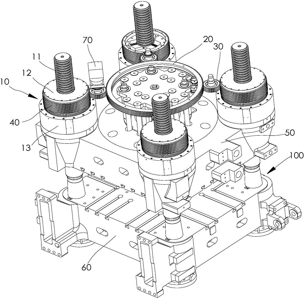
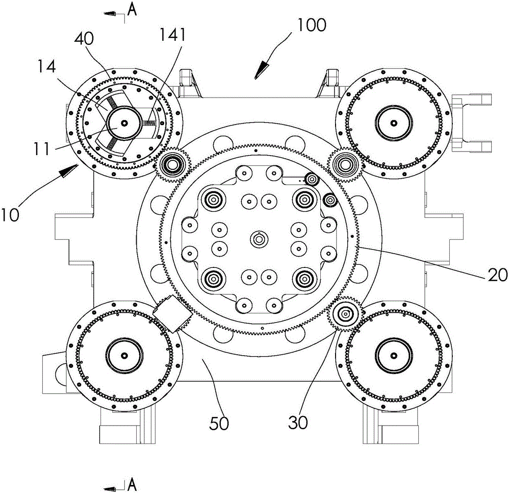
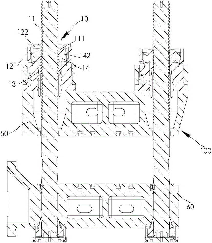
[0031] Such as Figure 1-7 A tie rod locking device 10 is shown, in this embodiment, the tie rod locking device 10 can be installed on the movable template 50 on the injection molding machine, including a tie rod 11, a plurality of locking blocks 14 and a first Drive mechanism, one end of the pull rod 11 is fixed on the fixed template 60 of the injection molding machine, the other end of the pull rod 11 is installed on the movable template 50, and the movable template 50 can be driven along the axial direction of the pull rod 11 under the drive of the oil cylinder on the injection molding machine. Movement to realize the opening and closing of the mold. In addition, the above-mentioned first driving mechanism is installed on the movable template 50, and a plurality of locking blocks 14 are arrayed outside the pulling rod 11 around the central axis of t...


PUM


Abstract

The invention discloses a pull rod locking device which comprises a pull rod, a plurality of locking blocks and a first driving mechanism, wherein the plurality of locking blocks are circumferentially arrayed outside the pull rod around the center axis of the pull rod; the first driving mechanism is used for driving a plurality of locking blocks to move along the radial direction of the pull rod so as to lock or loosen the pull rod. A clamping mechanism comprises a plurality of pull rod locking devices and a second driving mechanism; the second driving mechanism comprises a driving unit, a gear wheel synchronously coupled to a rotating shaft of a motor, and a plurality of pinions meshed with the gear wheel; tooth disks meshed with the pinions are arranged on the outer surfaces of rotary tables. According to the invention, rapid and convenient locking and loosening of the pull rod are achieved; a plurality of pull rod locking devices synchronously lock or loosen, so that efficiency is improved, and cost is saved.

Description

technical field [0001] The invention belongs to the technical field of injection molding and die-casting equipment, and in particular relates to a tie rod locking device and a mold locking mechanism. Background technique [0002] With the development of the plastics industry, the requirements for plastic products are getting higher and higher, and the two-platen injection molding machine has been widely used because of its simple structure and low cost. The clamping mechanism used in the two-platen injection molding machine generally includes a movable template, a fixed template, a tie rod connected between the movable template and the fixed template, and a tie rod locking device. Its working principle is to realize the connection and locking of the movable template and the tie rod through the tie rod locking device. When the tie rod locking device is opened, the movable template can move along the axial direction of the tie rod. [0003] However, the locking and releasing ...

Claims


Application Information

Patent Timeline
Patent Type & Authority Applications(China)
IPC IPC(8): B29C45/66
CPCB29C45/66B29C2045/662
Inventor 叶廷璧
Owner BORCH MACHINERY
Why Eureka
Try Eureka