

Wheel suspension for travelling crane, and crane
A technology of mobile cranes and wheel suspensions, which is applied to construction cranes, suspensions, motor vehicles, etc., and can solve problems such as asymmetric steering errors and affecting the stability of vehicle driving directions
- Summary
- Abstract
- Description
- Claims
- Application Information
AI Technical Summary
Problems solved by technology
Method used
Image

Examples
Embodiment Construction
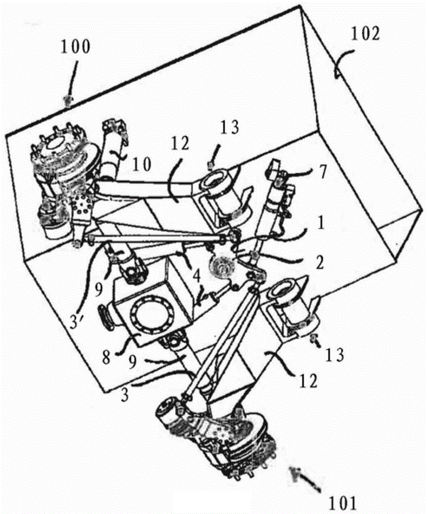
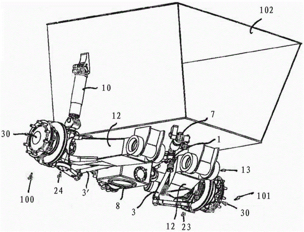
[0040] Figures 1 to 4 A first embodiment of a wheel suspension according to the invention is shown. compared to Figures 1 to 4 An example of the structure with a slight modification in the Image 6 and shown in 7 and 8. Identical components are provided with the same reference symbols in the figures.
[0041] The wheel suspension is formed as two independent single-wheel suspensions in the form of swing-arm axles (Schwingenachsen). Each wheel side 100 , 101 is supported elastically via a pivot arm 12 on a vehicle frame 102 about a horizontal pivot axis oriented transversely to the direction of travel. The wheel sides 100 , 101 are supported via steering knuckles 23 , 24 rotatably about vertical axes of rotation on the swing arm tip. The actuation of the swivel bearings on the wheel sides 100, 101 takes place by means of tie rod arms 20, 21 which are articulatedly connected to the individual tie rods 3, 3'. Both tie rods 3 , 3 ′ are hingedly mounted on a central reversi...
PUM
 Abstract
Description
Claims
Application Information