Grain conveyer special rotary disc
A technology of rotating discs and conveyors, applied in conveyors, rotary conveyors, transportation and packaging, etc., can solve the problems of ineffectiveness, small conveying range and low working efficiency of conveyors.
- Summary
- Abstract
- Description
- Claims
- Application Information
AI Technical Summary
Problems solved by technology
Method used
Image

Examples
Embodiment Construction
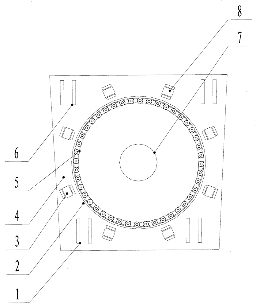
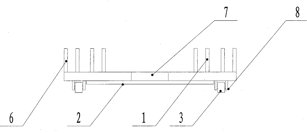
[0010] Products involved in the present invention such as figure 1 , figure 2 As shown, the double-layer rotating disk 4 is formed by welding two trapezoidal steel plates with support in the middle. A central hole 7 is provided in the center of the double-layer rotating disk 4 for installing rotating components. Two front support frame groups 6 and two rear support frame groups 1 are arranged on the top of the double-deck rotating disk 4, which are used to support the telescopic conveyor frame; the distance between the two front support frame groups 6 is larger than the distance between the two rear support frame groups 1 large, to increase the smoothness of the double-deck rotating disk 4. Eight rotating wheels 3 and passive gear rings 5 are arranged below the double-layer rotating disk 4, the rotating wheels 3 are evenly distributed in a circular array, and the rotating wheel bracket 8 is arranged under the double-layer rotating disk 4 by welding; Connect with swivel w...
PUM
 Abstract
Description
Claims
Application Information
PatSnap Eureka turns technology decisions into work you can execute. Powered by our Innovation Knowledge Graph, it runs expert workflows across engineering, life sciences, materials and intellectual property. Get your review-ready output in minutes.


