
Water purifier with turnover cover display window device

A technology for displaying windows and window devices, which is applied in the fields of water/sewage multi-stage treatment, water/sludge/sewage treatment, chemical instruments and methods, etc. problems, to achieve the effects of intuitive inspection and maintenance, simple machine structure, and stable assembly quality

Inactive Publication Date: 2016-08-24
杜也兵
View PDF4 Cites 5 Cited by
  • Summary
  • Abstract
  • Description
  • Claims
  • Application Information

AI Technical Summary

Problems solved by technology

In view of the limited size of the shell of the water purifier due to the limitation of the use of environmental space, usually less than 500 mm × 200 mm × 450 mm, the display control device is placed on the side elevation of the machine to affect the number of filter gallbladder settings, and cause problems in use and operation. inconvenient
Therefore, although the seat-type water purifier with the lower machine base has the characteristics of convenient extraction of the filter gall, this mode is rarely used.
However, the above-mentioned problems can be overcome by adopting a flip cover with a display window device and an operation control device to increase the operating surface at the top of the machine, but it brings a new problem, that is, the electric control device located on the flip cover and the lower machine base. The wiring connection with the display window device, the operation control device, and the water-passing electric control device is difficult due to the structural layout of the machine. The problem that the swing is easy to be damaged, and it is difficult to consider setting a display control device on the movable panel, and destroys the overall shape and appearance of the control panel or the shell, and is difficult to integrate. The above problems and defects seriously affect the shape and quality of the water purifier product. Beautiful, has become a taboo in product industrial design, and seriously affects the design and manufacture of water purifier products

Method used


Image

  • Water purifier with turnover cover display window device

Examples


Embodiment 1

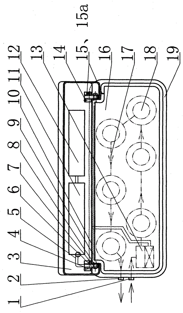
[0028] Example 1. In the accompanying drawings, three pre-closed filter gallbladders 18, and two RO reverse osmosis membrane bare gallbladders 18 adopting an open filter cartridge with a cover, and an open filter cartridge with a cover (not shown) are also used. The post activated carbon filter gallbladder 18 is connected with the water pipeline, and communicates with the machine base inlet and outlet 1,2 respectively to form the filter passage 17. The filter channel 17 is arranged on the bottom plate of the lower filter gall bin 16 . The water pipe butt joint device (not shown) connected in the filter channel 17 is provided with an upward butt joint water port and a respective downward water port of each corresponding filter bladder 18 for sealing insertion. A plurality of water passing control parts of the machine are fixedly connected under the water pipe docking device, and the water passing pipe interface of each water passing control part is connected to the correspondi...

Embodiment 2

[0041] Example 2. On the basis of Embodiment 1, the hinged swing mechanism and the swingable wire passing mechanism adopt a device in which the hollow shaft penetrates through the shaft holes of the vertical ears at both ends of the lower gallbladder bin 16 and the flip cover 3 and is hingedly matched. And the radial hole connecting the hollow shaft hole is set in the middle of the hollow shaft body; simultaneously, the lower line groove 9 and the radial hole of the hollow shaft body are set in the lower gallbladder bin 16 to form a wire passing channel correspondingly. When the vertical ear of the flip cover swings around the hollow shaft body, the wire connected to the electric control device 11 enters the hollow shaft body through one end port of the hollow shaft body, and then passes through the radial hole of the hollow shaft hole and enters the off-line of the gallbladder bin 16. The groove 9 is connected to the water control part in turn.

Embodiment 3

[0042] Example 3. On the basis of the above-mentioned embodiments, the hinged swing mechanism and the swingable wire passing mechanism adopt the flip cover 3 provided with vertical lugs with notched shaft holes and the hollow shaft body supported by the two vertical lugs of the lower gallbladder bin 16 is radially inserted and fixed. Articulated fittings. And on the shaft wall of the hollow shaft body, a radial wire-passing hole connecting the hollow shaft hole is set; at the same time, the lower line groove 9 is set in the lower gallbladder bin 16 to correspond to the radial wire-passing hole of the hollow shaft body to form a wire-passing channel . The wire connected to the electric control device 11 enters the hollow shaft body through one end port of the hollow shaft body, then passes through the radial wire hole of the hollow shaft hole and enters the downline slot 9 of the gallbladder bin 16, and then connects to the water control system. part.

[0043] As an improvem...


PUM


Abstract

The invention relates to the water treatment industry, in particular to drinking water filtration, and discloses a water purifier with a turnover cover display window device. The water purifier comprises filtering inner containers and a lower filtering inner container bin. The filtering inner containers are fixed into the lower filtering inner container bin through filtering inner container fastening devices. Water ports in the lower ends of all the filtering inner containers are connected front and back to form a filtering channel. The water purifier further comprises a turnover cover provided with the display window device, vertical lugs arranged on the lower filtering inner container bin and the turnover cover respectively, and a shaft. The shaft, the vertical lug of the lower filtering inner container bin and the vertical lug of the turnover cover form a hinge swing mechanism connected with the lower filtering inner container bin and the turnover cover in a matched mode. The display window device is either a single-display-window device arranged on one side of the turnover cover or a double-display-window device provided with a running state display window device and a detection maintenance state display window device.

Description

technical field [0001] The invention relates to the water treatment industry, in particular to the shell structure of the water purifier. Background technique [0002] As a very convenient horizontal water purifier, it can be placed on the countertop of the kitchen cabinet or placed in the cabinet. Just place the machine directly on the place of use, no need to drill holes to hang the machine. Because the filter gall is located above the machine base, it is more convenient to replace the filter gall, which is relatively time-saving and labor-saving. However, the biggest problem with the structure of the seat type water purifier is that the operating surface of the machine is small, the display window device and the operation control device can only be installed on the side elevation of the machine, and the top surface is used for extracting and replacing the filter bladder, and there is no place for parts put. In view of the limited size of the shell of the water purifier...

Claims


Application Information

Patent Timeline
IPC IPC(8): C02F9/02
Inventor 杜也兵冉伊虹
Owner 杜也兵
Learn More