Vibration isolator in floating slab track system and method for determining operating parameters of vibration isolator

A floating plate and vibration isolator technology, applied in the direction of tracks, roads, buildings, etc., can solve the problems of low natural frequency, impact of vibration isolation efficiency, rebound rise and so on

Inactive Publication Date: 2016-08-24
SOUTHWEST JIAOTONG UNIV
View PDF6 Cites 6 Cited by
  • Summary
  • Abstract
  • Description
  • Claims
  • Application Information

AI Technical Summary

Problems solved by technology

According to the "Technical Specifications for Floating Slab Tracks" (CJJ / T191-2012), the maximum vertical vibration displacement of the steel rail and the floating slab in the floating slab track shall not be higher than 4mm and 3mm respectively, so the steel spring of the traditional floating slab The stiffness is not allowed to be too low, which will greatly affect its vibration isolation efficiency
Moreover, according to the free vibration theory of the single-degree-of-freedom mass-spring system, the steel spring floating slab track has a lower natural frequency, and its low-frequency vibration damping effect near the natural frequency of the steel spring floating slab track is unsatisfactory, not only will not be weakened Instead, there will be a rebound phenomenon

Method used


Image

  • Vibration isolator in floating slab track system and method for determining operating parameters of vibration isolator
  • Vibration isolator in floating slab track system and method for determining operating parameters of vibration isolator
  • Vibration isolator in floating slab track system and method for determining operating parameters of vibration isolator

Examples


Embodiment example

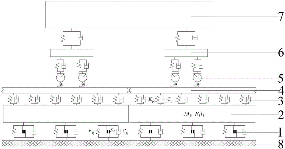
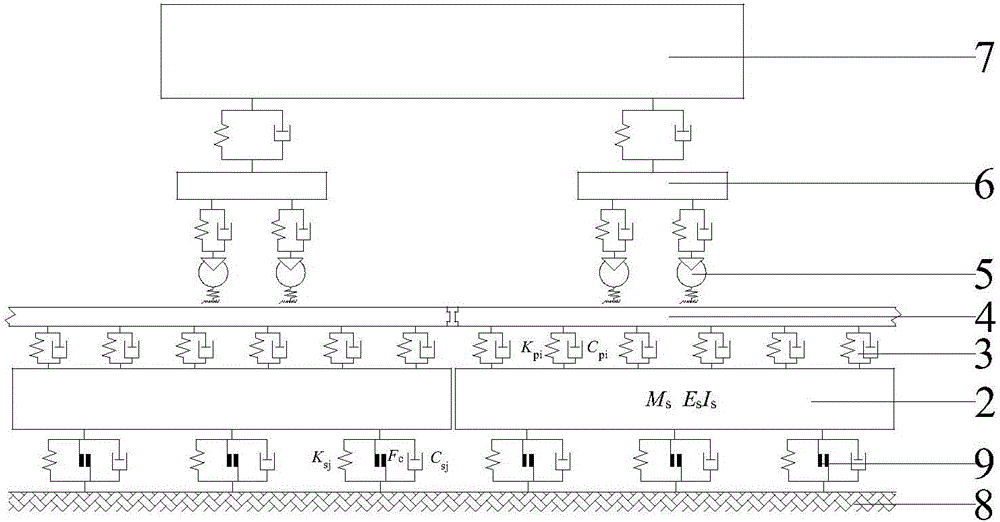
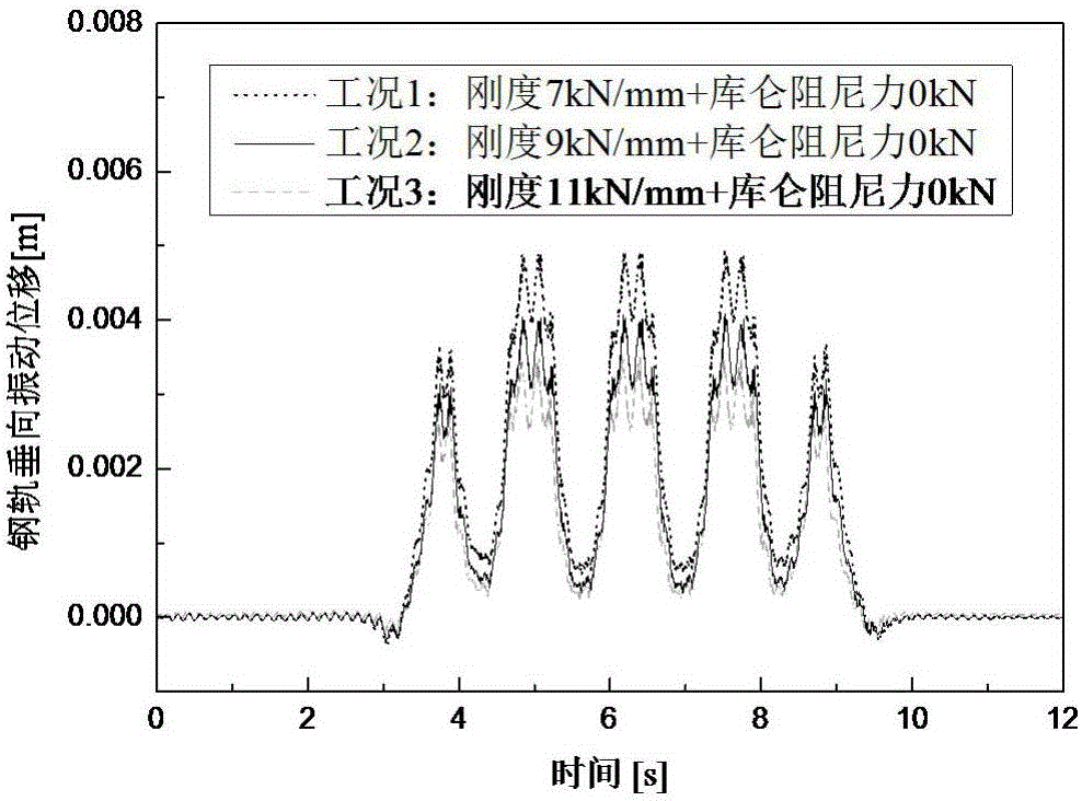
[0066] Implementation case: Taking the common steel spring floating slab track structure type in subway lines as an example, according to the method for determining the working parameters of the vibration isolator in the floating slab track system proposed by the present invention, carry out subway vehicle-controllable Coulomb damping floating Numerical simulation of the dynamic time-domain model of the slab-track coupling system, and a comparative analysis with the dynamic response of the steel spring floating slab track without Coulomb damping, to verify the feasibility and rationality of the design method for the controllable Coulomb damping working mode in the floating slab track sex.

[0067] The specific calculation conditions for the numerical simulation analysis are that the car body 7 is a type A subway car with a speed of 60km / h; the track structure includes a 60kg / m rail 4 and a rail fastener 3 (the dynamic stiffness coefficient is 60kN / mm, and the damping coefficien...


PUM


Abstract

The invention discloses a vibration isolator in a floating slab track system and a method for determining operating parameters of the vibration isolator. The vibration isolator is disposed between a floating slab of the floating slab track system and a track foundation, and comprises parallel steel springs, damping fluid and controllable Coulomb damping elements. The method comprises the steps: in the case of not considering Coulomb damp, establishing a vehicle-floating slab track coupling dynamics time-domain analysis model, taking maximum vertical vibrating displacement of a floating slab and a steel rail as a control index, determining a minimum supporting rigidity Ka of the floating slab without considering the Coulomb damp, then determining a displacement threshold value of floating slab by combining a floating slab vertical vibration displacement time travel curve characteristic under the minimum supporting rigidity working condition without considering the Coulomb damp, determining the magnitude of a Coulomb damping force and an operating time period, and finally calculating the minimum supporting rigidity Kb with the Coulomb damp by utilizing a vehicle-controllable Coulomb damp vibration isolator floating slab track coupling dynamic time-domain analysis model. The vibration isolation efficiency of the traditional steel spring floating slab track can be effectively improved.

Description

technical field [0001] The invention relates to the field of vibration reduction and noise reduction in rail traffic, in particular to a vibration isolator in a floating slab rail system and a method for determining its working parameters. Background technique [0002] Currently, steel spring floating slab tracks have the best vibration and noise reduction effects among rail transit vibration-damping tracks. The steel spring floating slab track structure is generally composed of steel rails, fasteners, reinforced concrete slabs, steel springs plus damping liquid vibration isolators and concrete bases. This type of structure uses fasteners to fix the rail on the reinforced concrete slab, and the slab is placed on an adjustable vibration isolator to form a mass-spring vibration isolation system. For linear resonators below the excitation frequency, the natural frequency of It has a significant isolation effect in frequency bands above 10 times. In engineering practice, the...

Claims


Application Information

Patent Timeline
Patent Type & Authority Applications(China)
IPC IPC(8): E01B19/00
CPCE01B19/00E01B2204/12
Inventor 韦凯王平赵东锋杨麒陆葛辉肖杰灵陈嵘赵才友肖建伟马道林易强
Owner SOUTHWEST JIAOTONG UNIV
Why Eureka
Try Eureka