Prefabricated component

A prefabricated component, non-structural technology, applied in the direction of building materials, etc., can solve the problems of complicated production and construction, lack of integrity, etc., and achieve the effect of facilitating the combination of new and old concrete, improving the integrity of the connection and direct force transmission

Inactive Publication Date: 2016-08-24
初明进
View PDF0 Cites 1 Cited by
  • Summary
  • Abstract
  • Description
  • Claims
  • Application Information

AI Technical Summary

Problems solved by technology

In the existing technology, there is a lack of integrity in the connection between prefabricated components, and the production and construction are cumbersome.

Method used


Image

  • Prefabricated component
  • Prefabricated component
  • Prefabricated component

Examples


Embodiment Construction

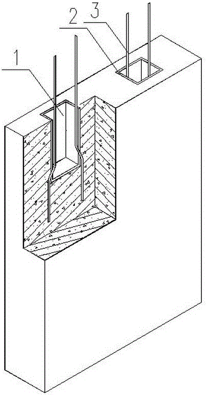
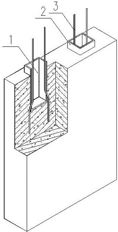
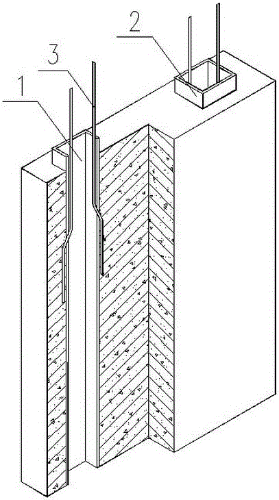
[0022] The prefabricated component of the present invention will be described in detail below with reference to the drawings and embodiments.

[0023] An embodiment of the prefabricated components proposed by the present invention, such as figure 1 The prefabricated component has a hole 1, the hole 1 has a lining 2, the lining 2 does not protrude from the prefabricated component, the side wall of the hole protrudes from the reinforcement bar 3, and the reinforcement bar 3 is anchored in the precast concrete on the side wall of the hole. Another embodiment of the prefabricated components proposed by the present invention, such as figure 2 , the inner lining 2 protrudes from the prefabricated component. The holes are non-through holes, such as figure 1 , figure 2 ; or the hole is a through hole, such as image 3 , Figure 4 , Figure 5 . exist Figure 4 Among them, the hole 1 is a through hole, and the lining 2 protrudes from both ends of the hole.

[0024] In another...


PUM


Abstract

The invention relates to a prefabricated component and belongs to the technical field of prefabricated concrete structures. A hole is formed in the prefabricated component. The prefabricated component is characterized in that a lining is arranged inside the hole; steel bars are arranged inside the hole and are anchored in the side wall concrete of the hole. Through the prefabricated component, the stress performance of the prefabricated concrete structures can be improved.

Description

technical field [0001] The invention belongs to the technical field of prefabricated reinforced concrete structures. Background technique [0002] Prefabricated concrete structures have high production efficiency and good quality, save resources and are conducive to sustainable development. The use of prefabricated concrete structures is the development direction of construction industrialization. [0003] The integrity of the connection between precast components is the key to ensuring the integrity of the precast concrete structure. In the prior art, the connection between prefabricated components has insufficient integrity, and the production and construction are cumbersome. Contents of the invention [0004] The purpose of the invention is to improve the connection performance between prefabricated components and improve the integrity of the assembled monolithic structure. [0005] To achieve the above object, the present invention proposes a prefabricated component...

Claims


Application Information

Patent Timeline
Patent Type & Authority Applications(China)
IPC IPC(8): E04C2/26
CPCE04C2/26
Inventor 初明进
Owner 初明进
Why Eureka
Try Eureka