Underground diaphragm wall I-shaped steel joint water stop control structure and construction method thereof

A technology of I-beam and control structure, which is applied to underwater structures, infrastructure engineering, artificial islands, etc., can solve the problems of low construction efficiency, labor-consuming and construction period, I-beam entrained glue, etc., so as to improve construction efficiency. , Waterproof quality assurance, good connection integrity

Pending Publication Date: 2020-05-29
CHINA CONSTR FIRST GROUP THE FIFTH CONSTR +1
View PDF0 Cites 1 Cited by
  • Summary
  • Abstract
  • Description
  • Claims
  • Application Information

AI Technical Summary

Problems solved by technology

[0003] The purpose of the present invention is to provide a ground connection wall I-shaped steel joint water-stop control structure and its construction method, which solves the problem that the existing ground-wall I-shaped steel joint construction water stop method is difficult to control the flow of concrete and the quality of water stop is difficult to control , consume a lot of manpower and construction period, and the problem of low construction efficiency. At the same time, it solves the problem of glue and mud entrained on the I-shaped steel after the excavation of the existing connecting width groove section, which is difficult to clean up, resulting in poor sealing effect of the I-shaped steel joint of the ground connection wall. question

Method used


Image

  • Underground diaphragm wall I-shaped steel joint water stop control structure and construction method thereof
  • Underground diaphragm wall I-shaped steel joint water stop control structure and construction method thereof

Examples


Embodiment Construction

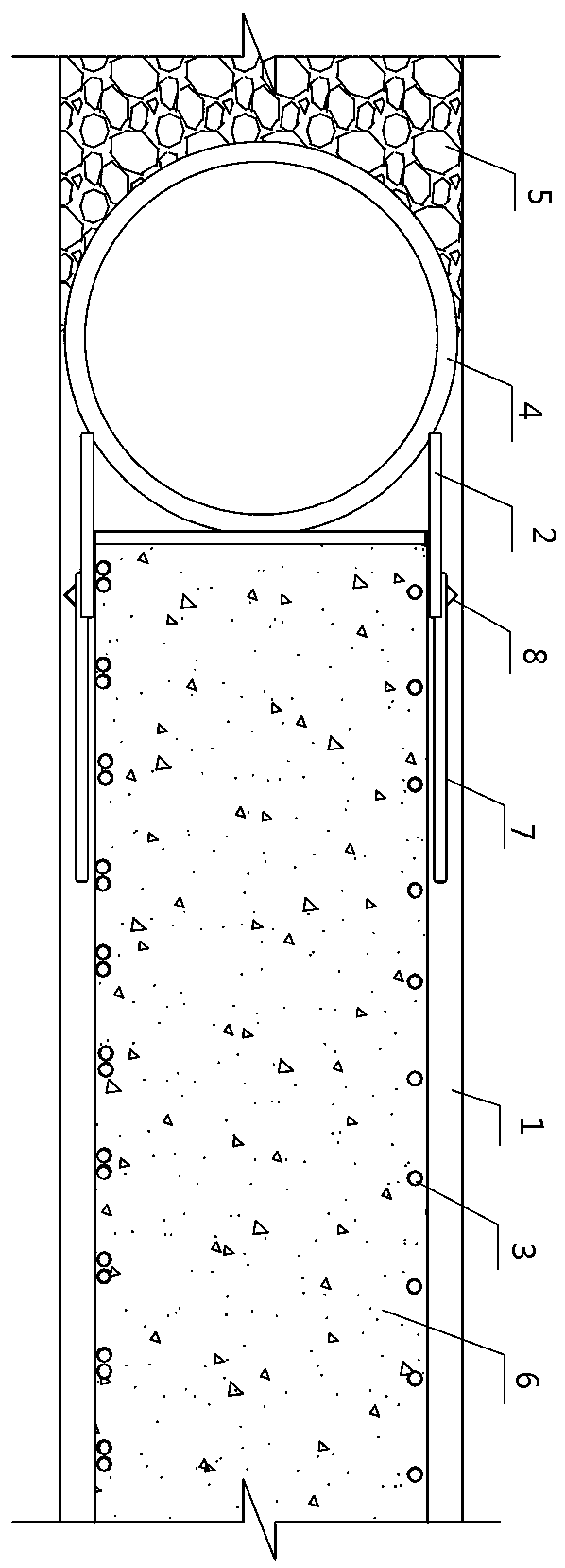
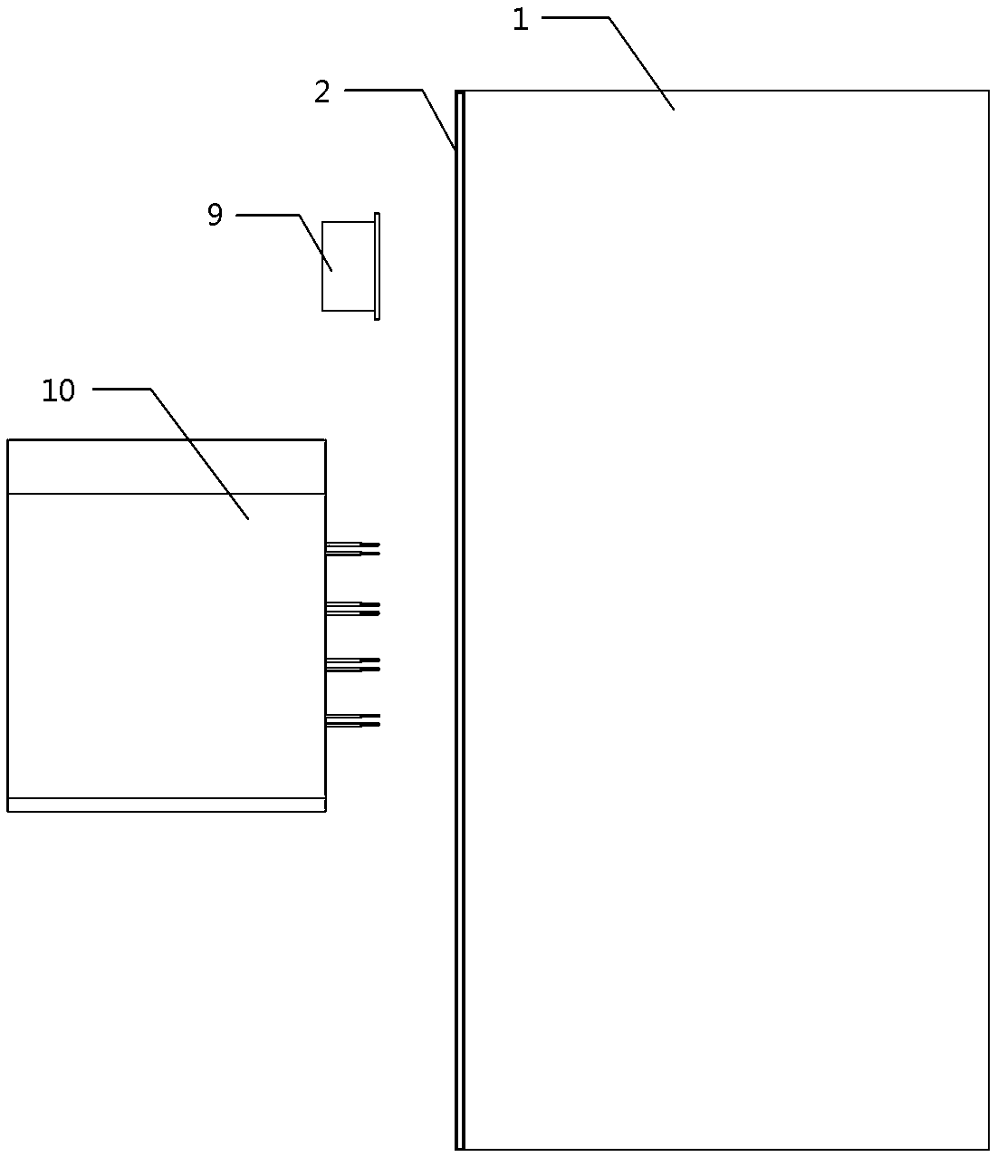
[0031] A ground connection wall H-shaped steel joint water-stop control structure and its construction method, for examples see figure 1 As shown, a ground connection wall I-shaped steel joint water-stop control structure includes an underground continuous wall groove section 1, an I-shaped steel joint 2 with a cross section facing upwards and vertically arranged in the underground continuous wall groove section 1, welded on The reinforcement cage 3 on one side of the web of the I-shaped steel joint 2, the concrete 6 poured on the reinforcement cage 3 and in the underground continuous wall groove section 1, the cross-section faces upwards, and is vertically closely attached to the I-shaped steel joint 2 The lock pipe 4 on the other side of the web plate, and the counter-pressed gravel 5 filled in the other side of the lock pipe 4; a pair of anti-slip plates 7 are welded symmetrically on the outer side of the flange plate of the I-shaped steel joint 2, The grout-stop bead 8 is ...


PUM


Abstract

The invention discloses an underground diaphragm wall I-shaped steel joint water stop control structure and a construction method thereof, and relates to the field of building construction. The underground diaphragm wall I-shaped steel joint water stop control structure comprises an underground diaphragm wall groove section, an I-shaped steel joint, a steel reinforcement cage, concrete, a port locking pipe and back pressing broken stones; the cross section of the I-shaped steel joint faces upwards, and the I-shaped steel joint is vertically arranged in the underground diaphragm wall groove section; the steel reinforcement cage is welded to one side face of a web of the I-shaped steel joint; the concrete is poured to the steel reinforcement cage and poured into the underground diaphragm wall groove section; the cross section of the port locking pipe faces upwards, and the port locking pipe is vertically and closely attached to the other side face of the web of the I-shaped steel joint;the other side of the port locking pipe is filled with the back pressing broken stones; and a pair of slurry stop plates are symmetrically welded to the outer side of a flange plate of the I-shaped steel joint, and slurry stop pressing strips are welded to the outer sides of the inner ends of the slurry stop plates. According to the underground diaphragm wall I-shaped steel joint water stop control structure and the construction method thereof, the problems that in an existing underground diaphragm wall I-shaped steel joint construction water stop method, round flowing of the concrete is difficult to control, the water stop quality is difficult to control, a large amount of manpower and construction period are consumed, and the construction efficiency is low are solved.

Description

technical field [0001] The invention relates to the field of building construction, in particular to a water-stop control structure for an I-shaped steel joint of a ground connection wall and a construction method thereof. Background technique [0002] The usual I-shaped steel joint water stop of the ground connection wall adopts I-shaped steel fixed slurry plate, I-shaped steel web foam filling and I-shaped steel web filling sandbags. This kind of conventional ground connection wall I-shaped steel joint water-stop construction method, the density problem between filling foam and filling sandbags and I-shaped steel has not been solved, and it is difficult to control the flow around the concrete, which consumes a lot of manpower and construction period, and the construction efficiency is low; Glue and mud are entrained on the beam, which is difficult to clean, resulting in poor water-stopping effect of the I-shaped steel joint of the ground wall. Contents of the invention ...

Claims


Application Information

Patent Timeline
Patent Type & Authority Applications(China)
IPC IPC(8): E02D5/20E02D29/16
CPCE02D5/20E02D29/16
Inventor 赵保森薛刚刘嘉茵汤德芸王彦明苏东黎赵亚军吕朋管海伦高云飞周佩祺张晓超
Owner CHINA CONSTR FIRST GROUP THE FIFTH CONSTR
Why Eureka
Try Eureka