Work method of roller shutter door lock

A working method and rolling door technology, which is applied in the field of rolling doors, can solve the problems of rolling doors without a special lock device, poor anti-theft effect, manual unlocking, etc.

Active Publication Date: 2016-08-24
蔡为达
View PDF6 Cites 3 Cited by
  • Summary
  • Abstract
  • Description
  • Claims
  • Application Information

AI Technical Summary

Problems solved by technology

[0003] The invention provides a working method of a rolling shutter door lock to overcome the disadvantages that the existing rolling shutter door has no special lock device and needs to be manually unlocked after adding a mechanical lock, the operation steps are cumbersome and the anti-theft effect is poor

Method used


Image

  • Work method of roller shutter door lock
  • Work method of roller shutter door lock
  • Work method of roller shutter door lock

Examples


Embodiment 1

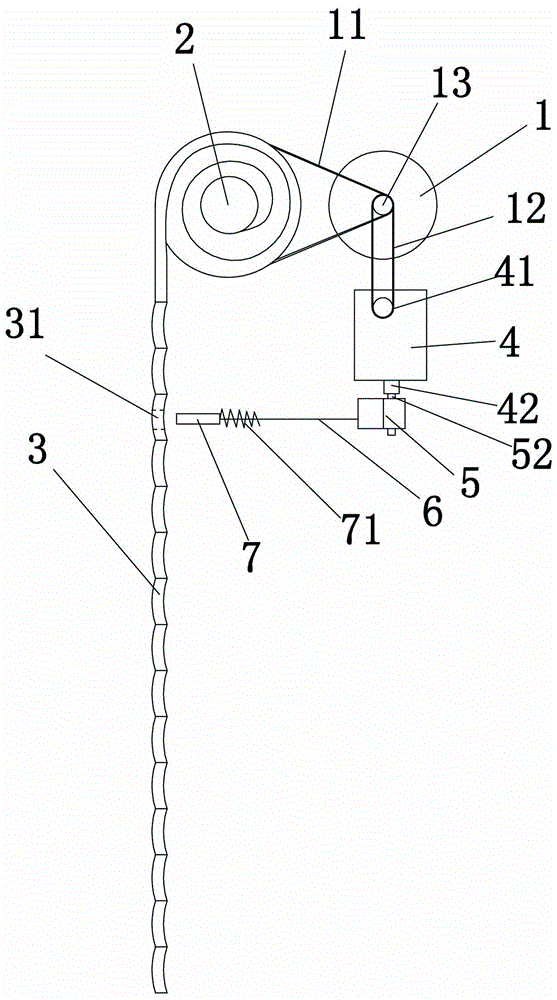
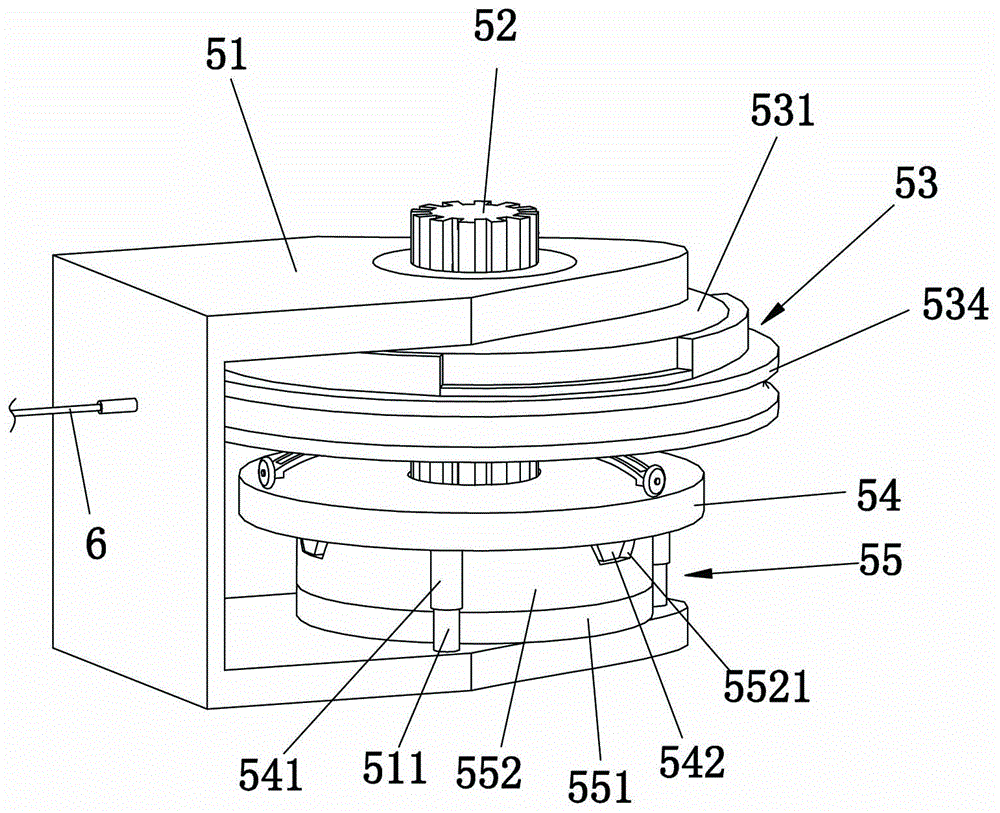
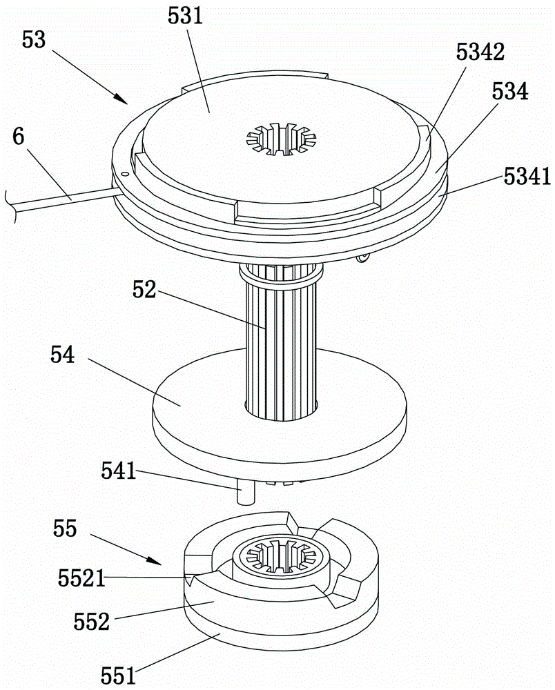
[0031] Reference Figure 1 to Figure 4 , A rolling door lock, comprising a lock core 7 and a spring 71 that moves the lock core 7 toward the rolling door 3 and locks the rolling door 3. The rolling door lock also includes a cable 6, a clutch device 5 and a motor. The clutch device includes a frame 51, a rotating shaft 52, a clutch assembly 53, a disc 54 and a damping wheel 55. The lock core 7 is a straight rod slidably arranged along its length, and the rolling door 3 is provided with an insertion hole 31 matching the lock core 7.

[0032] Reference Figure 2 to Figure 4 , The frame body 51 is in the shape of a letter and forms a mounting groove 512, and at least one column 511 is provided in the mounting groove 512.

[0033] Reference Figure 2 to Figure 4 The rotating shaft 52 is rotatably arranged in the mounting slot 51, and the rotating shaft 52 is driven by the above-mentioned motor.

[0034] Reference Figure 1 to Figure 6 The clutch assembly 53 includes a driving disc 531, ...

Embodiment approach

[0042] Reference Figure 7 , The rolling door lock includes a rolling door motor 1, an acceleration box 4, a clutch device 5, a cable 6, a spring 71 and a lock core 7. For the specific arrangement of the lock core 7, another specific implementation: the rolling door door lock also includes a holding block 10, a bracket 8 and at least one connecting rod 9. The lock core 7 is provided with a concave surface 32 that fits with the inner side of the rolling door 3. 的surface 72. One end of the connecting rod 9 is pivotally connected to the bracket 8, and the other end is pivotally connected to the lock core 7, and the lock core 7 is located obliquely below the bracket 8. The holding block 10 is held on the outer side of the rolling door 3 and cooperates with the lock core 7 to clamp the rolling door 3. When a thief uses a tool to pry open the rolling door 3, because the lock core 7 is arranged diagonally below the bracket 8 through the connecting rod 9, the more you pry the rolling d...


PUM


Abstract

The invention discloses a work method of a roller shutter door lock and relates to the technical field of roller shutter doors. The method includes the following steps that a roller shutter door motor drives a rotating shaft to rotate, a drive disc and a drive wheel are rotated along with the rotating shaft and drive a driven wheel to rotate; a disc is limited by a cylinder body and cannot rotate, and the driven wheel pushes the disc in the length direction of the rotating shaft; the end, provided with a roller, of a clutch lever moves towards a driven disc, so that the drive disc and the driven disc are close to each other and jointed, and at the moment, the driven wheel does not rotate along with the drive wheel; the driven disc rotates and coils an inhaul cable, a lock core is separated from a roller shutter door, and the roller shutter door lock can complete operation of unlocking or locking the roller shutter door independently. The roller shutter door lock has the advantages of being easy to operate, good in antitheft effect and the like.

Description

Technical field [0001] The present invention relates to the technical field of rolling shutter doors, in particular to a working method of a rolling shutter door lock. Background technique [0002] The door leaf of the rolling door is a movable door leaf composed of multiple door panels connected in series. The door leaf is rolled up and down to open and close the door. At present, the opening and closing of the rolling door is realized by the operation of the rolling door motor set on the rolling shaft of the rolling door. Usually, the rolling door does not have a separate The door lock completely relies on the self-locking function of the rolling door motor, which is easy to be opened and has poor anti-theft performance. In order to improve the anti-theft performance of the rolling door, mechanical locks are usually installed on the door leaf of the rolling door. Although the mechanical lock increases the anti-theft performance of the rolling shutter door, manual operation is ...

Claims


Application Information

Patent Timeline
Patent Type & Authority Applications(China)
IPC IPC(8): E06B9/70E05B47/00E05B65/00F16D13/52
CPCE05B15/00E05B47/0012E05B65/0021E05B2047/0026E06B9/70F16D13/38F16D13/52
Inventor 林水龙
Owner 蔡为达
Why Eureka
Try Eureka