Supercharge Your Innovation With Domain-Expert AI Agents!

Static wing unit and forced draught blower

A static-blade, axial-flow fan technology, applied in pump components, mechanical equipment, machines/engines, etc., to solve problems such as increased airflow loss

Active Publication Date: 2016-08-24
NIPPON DENSAN CORP
View PDF7 Cites 2 Cited by
  • Summary
  • Abstract
  • Description
  • Claims
  • Application Information

AI Technical Summary

Problems solved by technology

Therefore, there are cases where the loss of air flow becomes large due to the angle of the blades

Method used


Image

  • Static wing unit and forced draught blower
  • Static wing unit and forced draught blower
  • Static wing unit and forced draught blower

Examples


Embodiment Construction

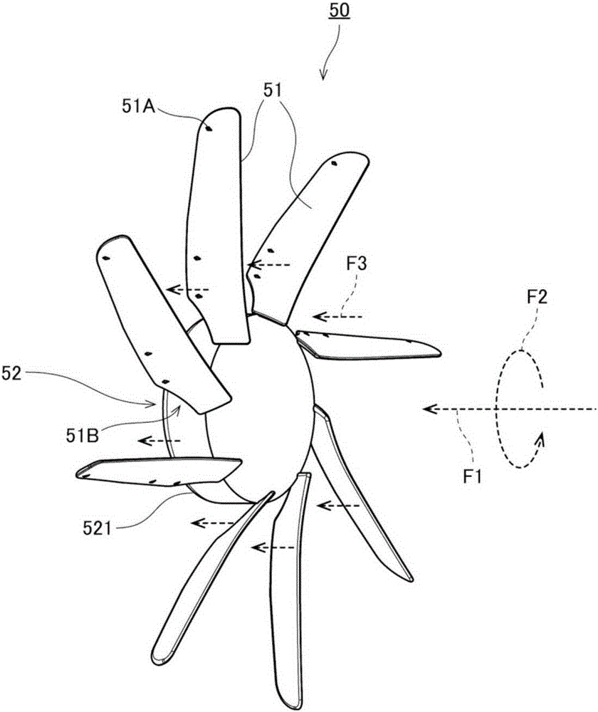
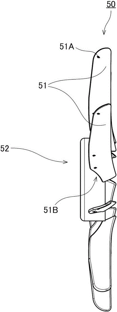
[0026] Examples of the air blower and the vane unit will be described below. In addition, in this description, directions parallel and substantially parallel to the axis of rotation of the axial fan are referred to as "axial directions", and directions perpendicular to and substantially perpendicular to the axis of rotation of the axial fan are referred to as "radial directions". ", and the direction along the circular arc centered on the axis of rotation of the axial flow fan is called "circumferential direction". In addition, in the present description, the shape and positional relationship of each part will be described with the axial direction as the front-rear direction and the stator blade unit side with respect to the axial fan as the front side. However, the definition of the front-rear direction does not intend to limit the installation direction of the air blower and the vane unit during use.

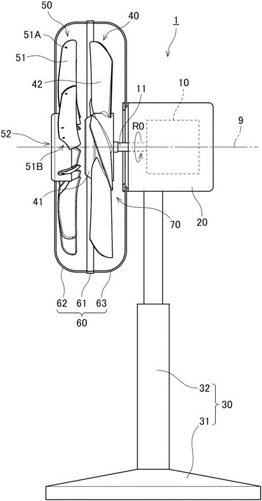
[0027] figure 1 It is a side view of the fan 1 having the vane unit 50 ...


PUM


Abstract

The invention relates to a static wing unit and a forced draught blower. The static wing unit is disposed in front of the axial direction of an axial fan. The static wing unit includes a plurality of rectifying blades extending radially outward from the vicinity of the rotation axis, and a switching mechanism for switching the position of the rectifying blades. The switching mechanism switches, by two or more stages, the relative position of outer end portions of the rectifying blades relative to the circumferential direction of inner end portions and the pitch angle of the rectifying blades relative to the plane orthogonal to the rotation axis. If a direct-acting component and a rotational component of an air flow generated from the axial flow fan collide with the rectifying blades of the static wing unit, the direct-acting component and the rotational component change directions in accordance with the posture of the rectifying blades. Therefore, the degree of diffusion or aggregation of the air flow can be changed by switching the relative position of the outer end portions of the rectifying blades relative to the circumferential direction of the inner end portions and the pitch angle of the rectifying blades relative to the plane orthogonal to the rotation axis.

Description

technical field [0001] The invention relates to a stationary wing unit and a blower. Background technique [0002] Conventionally, axial flow fans have been used in blowers such as fans and circulators. In the axial flow fan, the impeller is rotated by the driving force from the motor, and an air flow is generated in a direction substantially parallel to the rotation axis of the motor. In these air blowers, depending on the situation at the time of use, there are cases where it is desired to concentrate the airflow in a specific direction or to send the airflow to a distant place, and cases where it is desired to spread the airflow over a wide range. Therefore, conventionally, a structure for concentrating or diffusing the airflow generated by the axial fan has been proposed. [0003] For example, a conventional blower is described in Japanese Utility Model Publication No. H1-11994. In the air blower described in this gazette, a plurality of blades for adjusting the airfl...

Claims


Application Information

Patent Timeline
IPC IPC(8): F04D29/56F04D29/66F04D25/08
CPCF04D25/08F04D29/542F04D29/563F04D29/661
Inventor 竹本心路
Owner NIPPON DENSAN CORP
Features
  • R&D
  • Intellectual Property
  • Life Sciences
  • Materials
  • Tech Scout
  • Unparalleled Data Quality
  • Higher Quality Content
  • 60% Fewer Hallucinations
Learn More