
Steel guide rail structure used within wide temperature range and at high precision

A high-precision, wide-temperature technology, used in linear motion bearings, rotating parts that resist centrifugal force, bearings, etc., can solve problems such as failure to meet the accuracy requirements of steel guides, errors, affecting the connection between steel guides and non-steel bases, etc. , to achieve the effect of ensuring accuracy requirements and ensuring force requirements

Active Publication Date: 2016-08-24
苏州腾超机电设备有限公司
View PDF9 Cites 0 Cited by
  • Summary
  • Abstract
  • Description
  • Claims
  • Application Information

AI Technical Summary

Problems solved by technology

[0003] The steel guide rail is generally installed on the non-steel base through the screw fixing holes on it. The steel guide rail will produce slight deformation in a certain temperature range, which will affect the connection between the steel guide rail and the non-steel base. In the case of high-precision use, The deformation of the steel guide rail will cause errors in the operation process, which cannot meet the accuracy requirements of the steel guide rail.

Method used


Image

  • Steel guide rail structure used within wide temperature range and at high precision
  • Steel guide rail structure used within wide temperature range and at high precision

Examples


Embodiment Construction

[0015] The present invention is described below in conjunction with accompanying drawing.

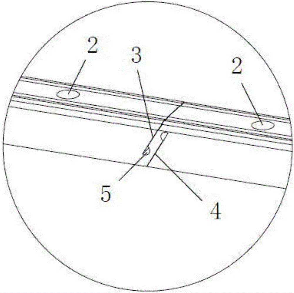
[0016] as attached Figure 1-2 As shown, the steel guide rail structure under a wide temperature range and high precision use state according to the present invention includes a non-steel base and a steel guide rail 1 arranged on the non-steel base; the steel guide rail 1 is provided with multiple screw fixing holes 2 evenly spaced; multiple sets of expansion joint structures are arranged on the steel guide rail 1, and three screw fixing holes 2 are spaced between adjacent expansion joint structures to ensure the service strength of the steel guide rail 1; The group expansion joint structures all include upper expansion joints 3 and lower expansion joints 4 parallel to each other, the upper expansion joints 3 extend downward from the upper surface of the steel guide rail 1, and the lower expansion joints 4 extend upward from the lower surface of the steel guide rail 1; Both the upper e...


PUM


Abstract

The invention discloses a steel guide rail structure used within a wide temperature range and at a high precision. The steel guide rail structure comprises a non-steel base and a steel guide rail which is arranged on the non-steel base; the steel guide rail is provided with a plurality of screw fixing holes which are arranged at uniform intervals; the steel guide rail is also provided with a plurality of groups of expansion joint structures; each expansion joint structure group comprises an upper expansion joint and a lower expansion joint which are parallel to each other; each upper expansion joint extends downwards from the upper surface of the steel guide rail; each lower expansion joint extends upwards from the lower surface of the steel guide rail. According to the steel guide rail structure used within wide temperature range and at high precision, the upper expansion joints and the lower expansion joints are respectively arranged on the upper and lower surfaces of the steel guide rail, so the deformation quantity of the steel guide rail, generated when temperature is changed, can be counteracted by the expansion joints in order to guarantee the linear precision requirement of the guide rail; the upper expansion joints and the lower expansion joints are obliquely arranged in parallel and are positioned between two adjacent mounting holes so that the force bearing requirement of the steel guide rail under a working state can be satisfied.

Description

technical field [0001] The invention relates to a steel guide rail structure, in particular to a steel guide rail structure under wide temperature range and high precision use state. Background technique [0002] A guide rail is a device that can bear, fix, and guide mobile devices or equipment and reduce friction; longitudinal grooves or ridges on the surface of the guide rail are used to guide and fix machine parts, special equipment, instruments, etc.; guide rails are also called slide rails , Linear guide rails, linear slide rails, used in linear reciprocating motion applications, have a higher rated load than linear bearings, and can bear a certain torque at the same time, and can achieve high-precision linear motion under high load conditions. [0003] The steel guide rail is generally installed on the non-steel base through the screw fixing holes on it. The steel guide rail will produce slight deformation in a certain temperature range, which will affect the connectio...

Claims


Application Information

Patent Timeline
Patent Type & Authority Applications(China)
IPC IPC(8): F16C29/00
CPCF16C29/005F16C2300/40
Inventor 温延培刘为周富强
Owner 苏州腾超机电设备有限公司
Learn More