Combined water level control valve without power source

A water level control, combined technology, applied in valve details, diaphragm valves, valve devices, etc., can solve the problems of easy to forget to turn off the water, labor and time consuming, water loss, etc., to achieve the effect of no power supply, sensitive response, and clever design

Inactive Publication Date: 2016-08-24
何风平 +2
View PDF0 Cites 0 Cited by
  • Summary
  • Abstract
  • Description
  • Claims
  • Application Information

AI Technical Summary

Problems solved by technology

[0002] Existing farmland irrigation and water control generally adopts digging a gap on the farmland ridge to release water, or pre-buried culverts on the ridge for water intake. The above two methods require manual blocking in time when the field water level meets the requirements. Water is labor-intensive and time-consuming. At the same time, it is easy to forget to turn off the water. At this time, a large amount of water will be lost. Therefore, it is imperative to develop automatic water control valves for farmland, which meets the water-saving requirements advocated by the country. condition

Method used


Image

  • Combined water level control valve without power source
  • Combined water level control valve without power source
  • Combined water level control valve without power source

Examples


Embodiment Construction

[0013] In order to further illustrate the present invention, it is introduced below in conjunction with the description:

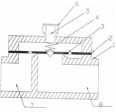
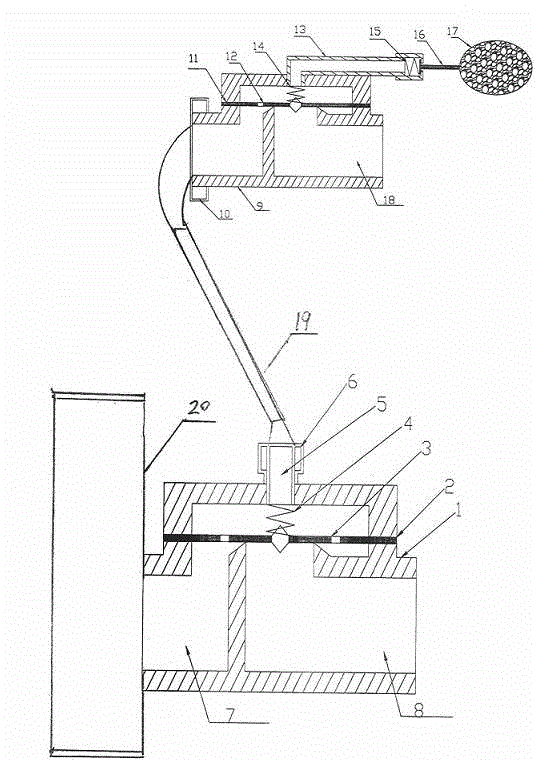
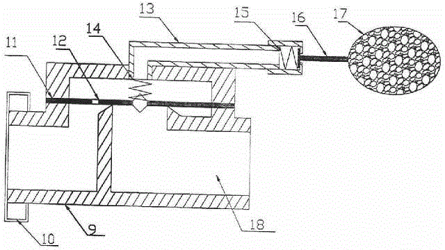
[0014] Refer to the attached figure 1 and figure 2 , image 3 , Combined water level control valve without power supply, the main valve includes valve body 1, diaphragm 2, equalizing pressure hole 3, return spring 4, pressure relief hole 5, union nut 6, water inlet 7, water outlet 8, secondary valve It includes valve body 9, union nut 10, die plate 11, pressure equalization hole 12, pressure relief conduit 13, return spring 14, pilot return spring 15, eccentric ejector rod 16, float 17, water outlet 18, connecting hose 19. In the inner cavity of the main valve 1, a diaphragm 2 is placed above the annular outlet. There are pressure equalization holes 3 on both sides of the diaphragm 2, and a return spring 4 is arranged in the hollow cavity between the diaphragm 2 and the valve cover. The center is provided with a pressure relief hole 5, a union nut 6, t...


PUM


Abstract

The invention relates to a combined water level control valve without a power source. When the combined water level control valve is used, at first, a primary valve is mounted on a water supply pipeline, a secondary valve is mounted in a field, a connecting hose is in butt joint with union nuts which are arranged on the primary valve and the secondary valve, the combined water level control valve without the power source is normally opened, and when a floating ball of the secondary valve drops, the planes of an ejecting rod and a guide pipe form a space naturally, so that the pressure of the upper cavity of a membrane of the secondary valve is released, and at the moment, the secondary valve is opened; then the pressure of the upper cavity of the primary valve is released through the connecting hose, and at the moment, the primary valve is opened; and when the water level of the field is reached, the floating ball floats under the action of water buoyancy, the round plane of the eccentric ejecting rod and the plane of the pressure releasing guide pipe are naturally matched and sealed, so that the pressure of the upper cavities of the sealed membranes cannot be released, under the double actions of pressure balancing holes of the membranes and a reset spring, water supply is stopped by virtue of the membranes of the secondary valve and the primary valve in sequence, and under non power source and unattended conditions, water supply and water supply stop are repeated so as to achieve the automatic supply and automatic supply stopping functions. Since the combined water level control valve is reasonable in structure, and convenient to mount, the combined water level control valve has a great market and popularization value.

Description

technical field [0001] The invention relates to the field of liquid level control, in particular to a powerless combined water level control valve for automatic farmland irrigation. Background technique [0002] Existing farmland irrigation water control generally adopts the method of digging a gap on the farmland ridge to release water, or pre-buying culverts on the field ridge to enter the water. The above two methods require manual blocking in time to stop the water when the field water level reaches the requirements. Therefore, it is time-consuming and labor-intensive. At the same time, it is easy to forget to turn off the water. At this time, the water source will be lost in large quantities. Therefore, it is imperative to develop automatic water control valves for farmland. condition. SUMMARY OF THE INVENTION [0003] The non-power combined water level control valve of the present invention is mainly used for pipeline pressure irrigation. [0004] In order to achie...

Claims


Application Information

Patent Timeline
Patent Type & Authority Applications(China)
IPC IPC(8): F16K7/12F16K31/18
Inventor 何风平肖海涛汤宝田
Owner 何风平
Why Eureka
Try Eureka