Flow metering system for oilfield production fluid

A technology of flow measurement and produced liquid, which is applied in the direction of volume measurement, liquid/fluid solid measurement, and measurement capacity, etc. It can solve the problems of large equipment maintenance, affecting measurement accuracy, and failure of medium compensation, etc., and achieves high liquid level measurement accuracy , Improve measurement accuracy and ensure safe use

Inactive Publication Date: 2016-08-24
王燕
View PDF6 Cites 3 Cited by
  • Summary
  • Abstract
  • Description
  • Claims
  • Application Information

AI Technical Summary

Problems solved by technology

[0002] At present, with the development of measurement and control technology, especially the refined management of the petroleum industry, the requirements for oil well production measurement are getting higher and higher; the traditional crude oil single-well flowmeter has a single design function. Although it has density compensation, the density compensation can only compensate Mixed liquid density, unable to calculate the ratio of oil and water in the mixed liquid, the actual application effect is not good
Due to the complex composition of the oilfield production fluid, it is often a gas-liquid two-phase, or even more complex, and when the medium contains gas, the gas error cannot be effectively solved, and the density measurement has no temperature and pressure compensation, and the medium cannot be compensated in real time, making the density measurement The error increases significantly, causing the error of the entire measurement system to be too large, which affects the measurement accuracy
In addition, the explosion-proof box and transmitter of the traditional crude oil single well flowmeter are exposed outside, and the exposed equipment is easily damaged in harsh environments, resulting in a large amount of equipment maintenance, increasing labor costs, and affecting the use of equipment

Method used


Image

  • Flow metering system for oilfield production fluid
  • Flow metering system for oilfield production fluid
  • Flow metering system for oilfield production fluid

Examples


Embodiment Construction

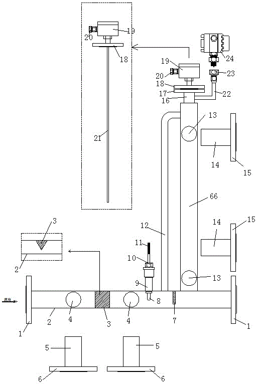
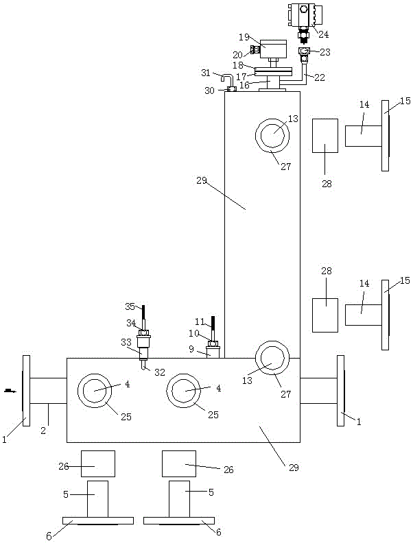
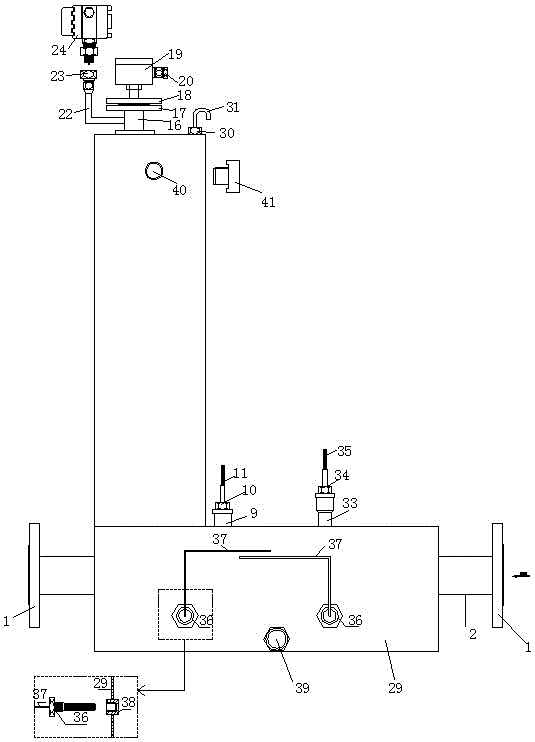
[0032] The present invention will be described in detail below with reference to the accompanying drawings and examples.

[0033] Such as Figure 1-Figure 6 As shown, the oilfield production fluid flow measurement system is composed of a flow measurement mechanism, a compensation mechanism and a data calculation mechanism connected to each other as a whole; Conveyor 50, a connection flange 1 is welded at both ends of the horizontal pipe 2, a wedge-shaped throttling piece 3 is welded inside the horizontal pipe 2, and a flow pressure hole 4 is respectively opened on both sides of the wedge-shaped throttling piece 3 on the horizontal pipe 2 , Weld the flow pressure connection pipe 5 on the flow pressure hole 4, weld the flow pressure connection flange 6 on the flow pressure connection pipe 5, and weld the flow pressure connection flange 6 through the flow transmitter to take the pressure flange fixing screw 53 is connected to the pressure-taking flange 48 of the flow transmitter...


PUM


Abstract

The invention discloses a flow metering system for oilfield production fluid. The flow metering system consists of a flow measurement mechanism, a compensation mechanism and a data calculation mechanism which are connected integrally. The system is very suitable for measuring liquid, such as mud, slurry, slurry oil, fuel oil, residual oil, coal tar and other fluids with high viscosity as well as suspended, easy-to-crystallize and dirty fluids, which is difficult to measure by a conventional flowmeter, to keep extremely high measurement precision and measurement stability. The metering system is novel in design and high in functionality; the difficulty in accurate metering of mixed media of oilfield production fluid, particularly medium oil / water components can be accurately metered, so that the efficiency of the metering system is improved, the investment for meters is reduced, and the demands of the metering system for various environments are met; the system is not required to be cleaned and maintained by a worker, so that human resources are saved, and the production efficiency is improved; the application prospect is considerable.

Description

technical field [0001] The invention belongs to the technical field of metering equipment, and relates to a metering system, in particular to a flow metering system for oilfield production fluid. Background technique [0002] At present, with the development of measurement and control technology, especially the refined management of the petroleum industry, the requirements for oil well production measurement are getting higher and higher; the traditional crude oil single-well flowmeter has a single design function. Although it has density compensation, the density compensation can only compensate The density of the mixed liquid cannot calculate the ratio of oil to water in the mixed liquid, and the actual application effect is not good. Due to the complex composition of the oilfield production fluid, it is often a gas-liquid two-phase, or even more complex, and when the medium contains gas, the gas error cannot be effectively solved, and the density measurement has no temper...

Claims


Application Information

Patent Timeline
Patent Type & Authority Applications(China)
IPC IPC(8): G01F15/00G01F15/02G01F15/14G01F1/36
CPCG01F1/36G01F15/00G01F15/022G01F15/14
Inventor 陆瑞翠
Owner 王燕
Why Eureka
Try Eureka