
Integrated encapsulating and potting device for sensor and operation method thereof

A sensor and potting technology, applied in measurement devices, electrical devices, instruments, etc., can solve the problems of limited number of potting and sealing wooden frame shells, waste of labor and material costs, unfavorable process flow, etc., to save labor and materials. , space saving, process saving effect

Inactive Publication Date: 2016-08-24
JURONG BOYUAN ELECTRONICS
View PDF6 Cites 0 Cited by
  • Summary
  • Abstract
  • Description
  • Claims
  • Application Information

AI Technical Summary

Problems solved by technology

[0003] In the prior art, during the entire production process of encapsulation and potting, the wiring harness needs to be tied and dismantled twice, the production process is cumbersome and wastes labor and material costs, and at the same time, the encapsulated products need to be put into the casing one by one , the efficiency is relatively low, and the number of shells placed on the potting wooden frame is limited. During the production process, a large number of wooden frames are required to occupy space and are not conducive to the circulation of subsequent processes.

Method used


Image

  • Integrated encapsulating and potting device for sensor and operation method thereof
  • Integrated encapsulating and potting device for sensor and operation method thereof
  • Integrated encapsulating and potting device for sensor and operation method thereof

Examples


Embodiment 1

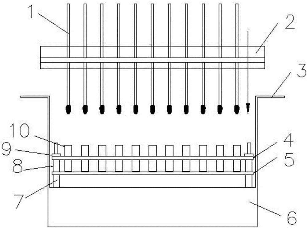
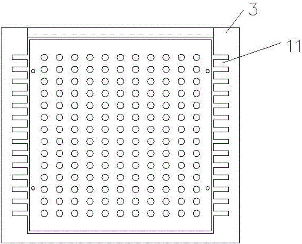
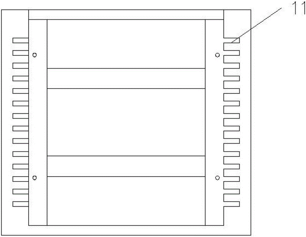
[0033] Embodiment one: if figure 1 and 2As shown, the present invention includes a carrier frame 6 and an encapsulation plate 2. The middle part of the carrier frame 6 is concave and protruding on both sides, and the protruding part is a side structure 3. Several first grooves 11 are provided on the edge structure, and the encapsulation plate 2 Placed in the first groove 11 of the side structure 3, several second grooves 13 are provided on one side of the enveloping plate 2, and the housing placement plate 4 is provided in the middle of the carrier frame 6 and fixed by screws 9. The shell placement plate 4 is provided with no less than 20 holes 12 , and shells 10 are placed in the holes 12 , and each shell 10 corresponds to a component 1 placed in the second groove 13 on the encapsulation plate 2 . Complete the encapsulation by setting the encapsulation plate 2 and the potting by the carrier frame 6, so that the encapsulation and potting can be realized in one device at the s...

Embodiment 2

[0043] Embodiment 2: The present invention includes a carrier frame 6 and an encapsulation plate 2. The middle part of the carrier frame 6 is concave and protruding on both sides, and the protruding part is a side structure 3. Several first grooves 11 are opened on the edge structure, and the encapsulation plate 2 is placed in the first groove 11 of the side structure 3, a plurality of second grooves 13 are arranged on one side of the encapsulating plate 2, and a shell placement plate 4 is arranged in the middle of the carrier frame 6 and fixed by screws 9, so that The housing placement plate 4 is provided with no less than 20 holes 12, housings 10 are placed in the holes 12, and each housing 10 corresponds to a component 1 placed in the second groove 13 on the encapsulation board 2. Complete the encapsulation by setting the encapsulation plate 2 and the potting by the carrier frame 6, so that the encapsulation and potting can be realized in one device at the same time, without...

Embodiment 3

[0055] Embodiment 3: The present invention includes a carrier frame 6 and an encapsulation plate 2. The middle part of the carrier frame 6 is concave and protruding on both sides, and the protruding part is a side structure 3. Several first grooves 11 are opened on the edge structure, and the encapsulation plate 2 is placed in the first groove 11 of the side structure 3, a plurality of second grooves 13 are arranged on one side of the encapsulating plate 2, and a shell placement plate 4 is arranged in the middle of the carrier frame 6 and fixed by screws 9, so that The housing placement plate 4 is provided with no less than 20 holes 12, housings 10 are placed in the holes 12, and each housing 10 corresponds to a component 1 placed in the second groove 13 on the encapsulation board 2. Complete the encapsulation by setting the encapsulation plate 2 and the potting by the carrier frame 6, so that the encapsulation and potting can be realized in one device at the same time, without...


PUM

PropertyMeasurementUnit
Thicknessaaaaaaaaaa
Widthaaaaaaaaaa

Abstract

The invention discloses an integrated encapsulating and potting device for a sensor. The integrated encapsulating and potting device is characterized in that a plurality of first grooves are formed in an edge structure on each of the two sides of a bearing frame; an encapsulating plate is placed in the first grooves, and a plurality of second grooves are formed in one side of the encapsulating plate; a shell placing plate is arranged in the middle of the bearing frame and is fixed by a screw, at least 20 holes are formed in the shell placing plate, and a shell is placed in each of the holes; each shell corresponds to a component placed in the corresponding second groove in the encapsulating plate. The operation method comprises the following steps: 1, placing the components in the second grooves in the encapsulating plate and encapsulating; 2, fixing the shell placing plate through the screw on the bearing frame; 3, adjusting a sleeve and the screw and adjusting the position of the shell placing plate; 4, placing the shell on the shell placing plate and placing the whole encapsulating plate on the bearing frame; 5, encapsulating and solidifying the bearing frame. The integrated encapsulating and potting device disclosed by the invention is simple, convenient and quick to operate, low in material and manpower consumption, and can improve the efficiency, save the space and facilitate subsequent process flow.

Description

technical field [0001] The invention relates to the field of sensor production, in particular to a device for integrating encapsulation and potting in the production process of a temperature sensor and an operation method thereof. Background technique [0002] After the thermistor or chip is welded with the wire, it needs to be insulated and withstand voltage protection, that is, encapsulated, and then encapsulated, that is, potted in the shell to make a temperature sensor. Before encapsulating, the products to be encapsulated must be arranged in an orderly manner. On the encapsulating wooden frame, wrap the thermistor, lead wires and the exposed parts of the welding with glue. After it is completely cured, remove all the encapsulated products from the wooden frame, and then wrap the encapsulated product one by one. One by one is put into the casing and then potted. During the potting process, the wires still need to be fixed on the potting wooden frame, and then all of them...

Claims


Application Information

Patent Timeline
IPC IPC(8): G01K7/22
CPCG01K7/22
Inventor 刘刚王梅凤汤成平
Owner JURONG BOYUAN ELECTRONICS
Learn More