DC charging connector and connection method thereof

A DC charging and connector technology, which is applied in the direction of vehicle connector, connection device connection/disconnection, connection, etc., can solve the problem that the safety and functionality cannot meet the market demand, the abnormal charging of the connector is interrupted, and there are potential safety hazards. and other problems, to achieve the effect of improving charging safety and personnel safety, facilitating plugging and unplugging, and increasing charging stability.

Active Publication Date: 2016-08-24
GUANGZHOU ZHICHONG AMPEREX TECH CO LTD
View PDF7 Cites 16 Cited by
  • Summary
  • Abstract
  • Description
  • Claims
  • Application Information

AI Technical Summary

Problems solved by technology

[0003] At present, the electric vehicle charging connectors on the market are prone to accidental pull-out during the charging process, and it is not conducive to holding, and it is inconvenient to plug in and out; it is easy to slip during the plug-in process, and it is inconvenient to use; when charging When plugged into the electric vehicle charging socket, the current will be turned on immediately, which may cause potential safety hazards; during the charging process, due to the misoperation of the staff, the connector is accidentally pulled out, resulting in abnormal charging interruption
With the continuous improvement of charging mode and safety requirements of electric vehicles, more and more charging connectors cannot meet the market demand in terms of safety and functionality when charging with vehicles. In 2016, with the standard revision of charging connectors and Safety performance requirements, there is an urgent need for a charging connector that meets the above requirements

Method used


Image

  • DC charging connector and connection method thereof
  • DC charging connector and connection method thereof
  • DC charging connector and connection method thereof

Examples


Embodiment

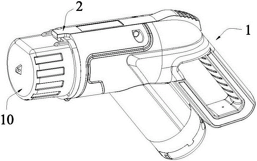
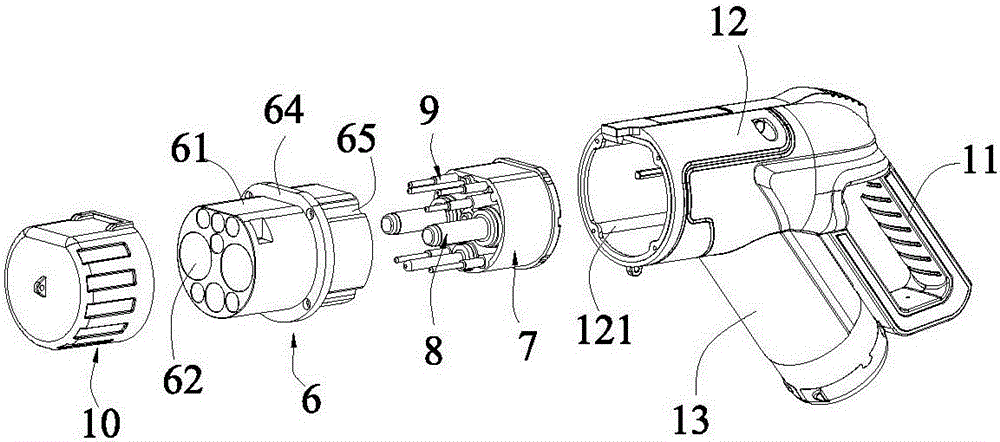
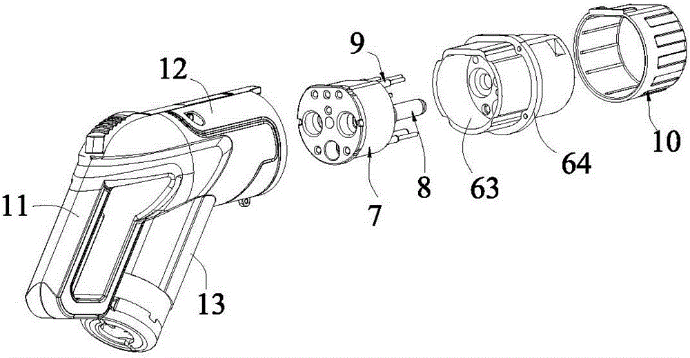
[0027] Example: see Figure 1 to Figure 4 , a DC charging connector provided in this embodiment, which includes a housing 1, a mechanical lock 2, a safety switch 3, an electronic lock 4, a locking feedback switch 5, a charging interface 6, an interface frame 7 and a The current terminal 8 on the frame 7, the housing 1 includes a ring-shaped handle portion 11 and a mounting portion 12 connected to the ring-shaped handle portion 11, the charging interface 6 is arranged at the end of the mounting portion 12, The interface inner frame 7 is arranged in the installation part 12, and the current terminal 8 on it extends into the charging interface 6, the mechanical lock 2 is arranged on the installation part 12, and one end of the mechanical lock 2 extends On the charging interface 6, a locking hook 24 is provided, and the other end extends in the opposite direction and is provided with a pressing part 25 that can make the locking hook 24 go up and release when pressed. The electroni...


PUM


Abstract

The invention discloses a DC charging connector and a connection method thereof. The DC charging connector comprises a shell, a mechanical lock, a safety switch, an electronic lock, a locking feedback switch, a charging interface, an interface inner frame and current terminals, wherein the current terminals are arranged on the interface inner frame. The DC charging connector is ingenious in structural design; the mechanical lock, the safety switch, the electronic lock and the locking feedback switch are reasonably arranged to form multi-protection; energization in the plugging process is avoided, so that sparks are avoided; the potential safety hazard is completely eradicated; the DC charging connector does not easily fall off after being coupled; and the charging stability is good. After the electronic lock works to be locked, a locking confirmation signal is fed back to a charging pile through the locking feedback switch, and then charging is carried out, so that the phenomena of abnormal charging interrupt and the like since the DC charging connector is accidentally unplugged due to a misoperation are avoided; and the charging safety and the personnel safety are greatly improved. Furthermore, the interface temperature in the charging process can be constantly monitored through a temperature sensor and can be fed back to the charging pile, so that the charging safety of the DC charging connector and a vehicle is greatly improved.

Description

technical field [0001] The invention relates to the technical field of charging connectors for electric vehicles, in particular to a DC charging connector applied to electric vehicles and a connection method thereof. Background technique [0002] Due to the wide range of energy sources, quiet running, and no pollution emissions, electric vehicles have attracted more and more attention from various automobile manufacturers, and they have launched household electric vehicles one after another. [0003] At present, the electric vehicle charging connectors on the market are prone to accidental pull-out during the charging process, and it is not conducive to holding, and it is inconvenient to plug in and out; it is easy to slip during the plug-in process, and it is inconvenient to use; when charging When plugged into the electric vehicle charging socket, the current will be turned on immediately, which may cause potential safety hazards; during the charging process, due to the mi...

Claims


Application Information

Patent Timeline
Patent Type & Authority Applications(China)
IPC IPC(8): H01R13/70H01R13/639H01R13/66H01R13/629H01R13/52H01R43/26B60L11/18
CPCB60L53/16H01R13/5202H01R13/5213H01R13/629H01R13/639H01R13/6683H01R13/70H01R43/26H01R2201/26Y02T10/70Y02T10/7072Y02T90/14
Inventor 彭建华
Owner GUANGZHOU ZHICHONG AMPEREX TECH CO LTD
Why Eureka
Try Eureka