
Endoscope objective optical system

An optical system and endoscope technology, applied in the field of objective optical systems, can solve the problems of difficult focus adjustment, inability to obtain high-definition images, narrowing of depth, etc., and achieve the effect of easy focus adjustment

Active Publication Date: 2016-08-24
OLYMPUS CORP
View PDF8 Cites 5 Cited by
  • Summary
  • Abstract
  • Description
  • Claims
  • Application Information

AI Technical Summary

Problems solved by technology

[0003] In addition, in general, when the pixel pitch of the imaging element is small, high-resolution images cannot be obtained unless Fno is reduced and a bright objective optical system is used.
On the other hand, when set to a bright objective optical system, the depth becomes narrow and it is difficult to adjust the focus
In addition, in the objective optical system, it is difficult to obtain high image quality and high definition when the focus position is shifted after positioning due to the curing shift of the adhesive, the influence of the focus position adjustment device, etc. image

Method used


Image

  • Endoscope objective optical system
  • Endoscope objective optical system
  • Endoscope objective optical system

Examples


Embodiment 1

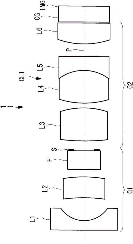
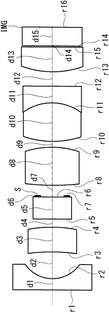
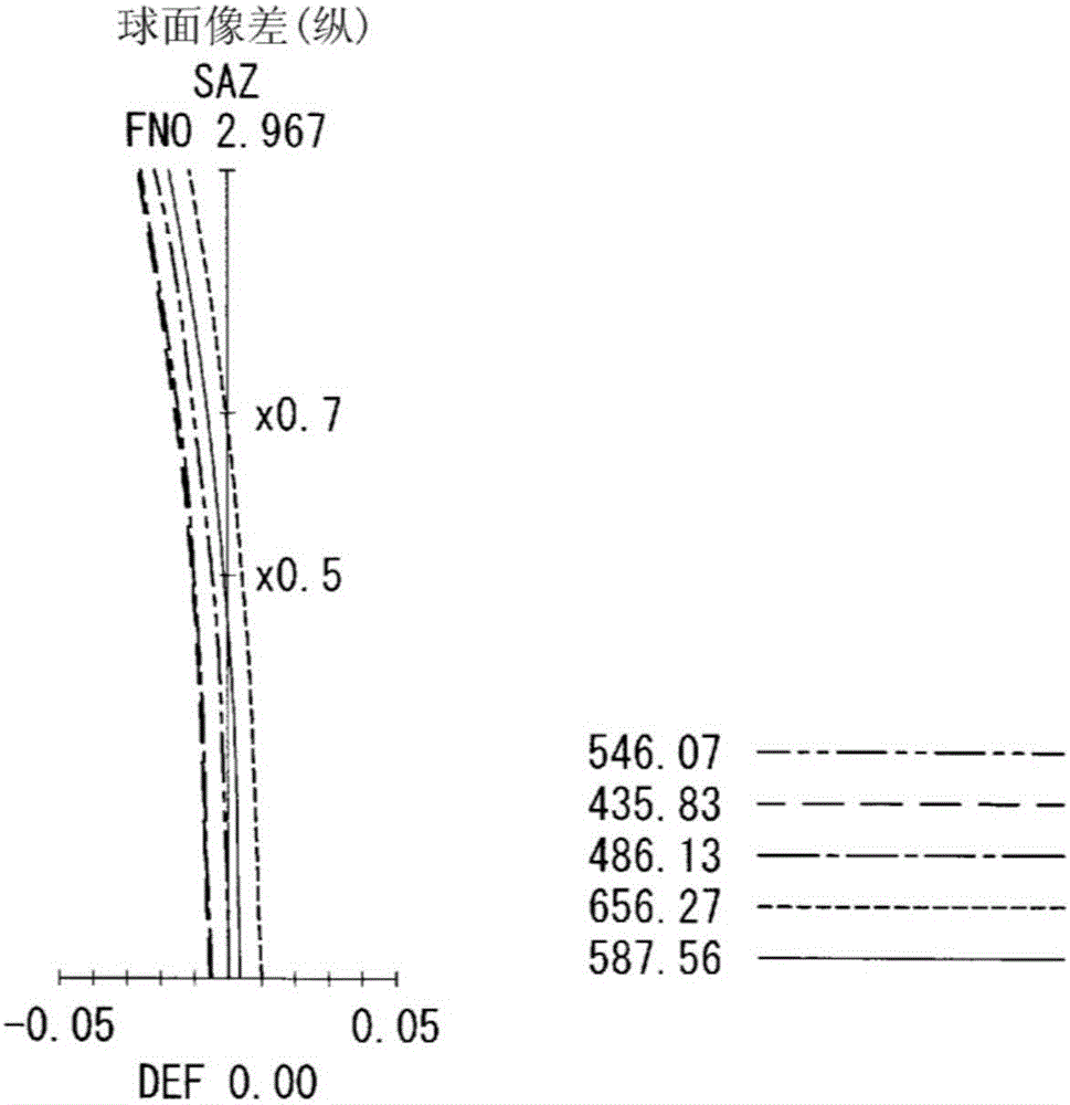
[0170] figure 2 The overall configuration of the endoscope objective optical system according to Embodiment 1 of the present invention is shown in , and the lens data are shown below. in addition, Figure 3A ~ Figure 3D Aberration graphs of the endoscope objective optical system according to this embodiment are shown in .

[0171] lens data

[0172]

[0173] various data

[0174]

Embodiment 2

[0176] Figure 4 The overall configuration of the endoscope objective optical system according to Embodiment 2 of the present invention is shown in , and the lens data are shown below. in addition, Figure 5A ~ Figure 5D Aberration graphs of the endoscope objective optical system according to this embodiment are shown in .

[0177] lens data

[0178]

[0179] various data

[0180]

Embodiment 3

[0182] Image 6 The overall configuration of the endoscope objective optical system according to Embodiment 3 of the present invention is shown in , and the lens data are shown below. in addition, Figure 7A ~ Figure 7D Aberration graphs of the endoscope objective optical system according to this embodiment are shown in .

[0183] lens data

[0184]

[0185] various data

[0186]


PUM


Abstract

The purpose of the present invention is to reduce the diameter of an endoscope objective optical system while facilitating focus adjustment and obtaining bright, wide-angle and high-definition image quality. The endoscope objective optical system (1) comprises, in order from the object-side, a front group (G1) having a negative refractive power, a brightness stop (S), and a rear group (G2) having a positive refractive power. The front group includes, in order from the object-side, a first lens (L1) which is a single lens having a negative refractive power and a second lens (L2) which is a single lens having a positive refractive power. The rear group (G2) includes a third lens (L3) which is a single lens having a positive refractive power, a cemented lens (CL1) created from a combination of a fourth lens (L4) having a positive refractive power and a fifth lens (L5) having a negative refractive power, and a sixth lens (L6) having a positive refractive power. The surface of the first lens facing the object is a flat surface, the second lens is meniscus-shaped, and the sixth lens is cemented to an imaging element. The endoscope objective optical system (1) satisfies the following conditional expression: 4 < Fno F6 / F1_5 < 500...(1) Where, Fno is the effective F-number of the endoscope objective optical system; F6 is the focal length of the sixth lens; and F1_5 is the composite focal length of the first to fifth lenses.

Description

technical field [0001] The invention relates to an objective optical system, in particular to an endoscope objective optical system applied to a medical endoscope. Background technique [0002] In recent years, miniaturization and high image quality of endoscopes have been progressing from the viewpoint of reducing the burden on patients and improving diagnostic accuracy. Therefore, as imaging elements for endoscopes, high-pixel and small-sized imaging elements (for example, CCD, CMOS, etc.) have been developed, and the pixel pitch thereof has been reduced year by year. With the shrinking of the pixel pitch, the objective optical system for endoscopes is also required to be miniaturized while satisfying optical performances such as widening the angle of view and correcting aberrations. [0003] In addition, generally, when the pixel pitch of an imaging element is small, a high-definition image cannot be obtained unless Fno is reduced and a bright objective optical system is...

Claims


Application Information

Patent Timeline
Patent Type & Authority Applications(China)
IPC IPC(8): G02B13/04
CPCG02B13/04A61B1/00188A61B1/04G02B21/02G02B23/2407G02B23/2423G02B23/243G02B23/2484G02B27/0081G02B5/005G02B9/62G02B27/0025
Inventor 牛尾恭章
Owner OLYMPUS CORP
Learn More