Football ejector

A catapult and football technology, applied in sports accessories and other directions, can solve the problems affecting the career development of football players, poor training effect, low training efficiency of football players, etc., to promote rapid mastery, improve training efficiency, and good training effect. Effect

Pending Publication Date: 2016-08-31
JIANGXI NORMAL UNIVERSITY
0 Cites 0 Cited by

AI-Extracted Technical Summary

Problems solved by technology

[0002] Football is a team sport that many people like. In daily training, athletes need a trainer to pass the ball to the football player to complete various technical actions. However, during training, the trainer cannot m...

Abstract

The invention discloses a football ejector. A shell (8) is in a hollow fan shape. A second stepping motor (11) is arranged on the bottom face of the inner cavity of the shell (8). One side of the second stepping motor (11) is connected with a second gear (10) through a rotating shaft. The upper portion of the second gear (10) is connected with a first gear (9). One side of the first gear (9) is fixedly connected with a rotating rod (7). The rotating rod (7) is connected with the inner wall of the shell (8) through a plurality of rolling bearings. The angle and strength of football ejecting are adjusted through the two stepping motors, so an ejected football can be passed to a football sportsman at fixed strength and fixed angle, training efficiency of football sportsmen is greatly improved, training effect is better, and football sportsmen are effectively encouraged to rapidly master various skills.

Application Domain

Technology Topic

Training effectFixed angle +3

Image

  • Football ejector
  • Football ejector

Examples

  • Experimental program(1)

Example Embodiment

[0012] The following will be attached figure 1 , 2 To explain in detail the beneficial effects of the present invention, which aims to help reading
[0013] Readers have a better understanding of the essence of the present invention, but cannot limit the implementation and protection scope of the present invention.
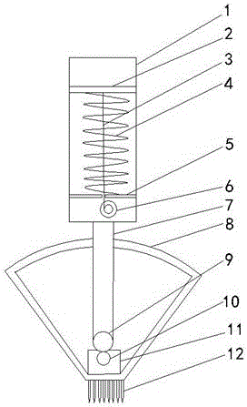
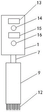
[0014] The casing (8) is a hollow sector. The bottom surface of the inner cavity of the casing (8) is provided with a stepping motor (11). One side of the stepping motor (11) is connected to the second gear (10) and the second gear (10) through a shaft. ) The upper part is connected to gear one (9), one side of gear one (9) is fixedly connected to the rotating rod (7), the rotating rod (7) is connected to the inner wall of the housing (8) through several rolling bearings, and the upper end of the rotating rod (7) penetrates the shell On the upper surface of the body (8), the top end of the rotating rod (7) is fixedly connected to the ejection barrel (1), the ejection barrel (1) is a hollow cylinder, and a power switch is provided on one side of the outer wall of the ejection barrel (1) (14), power switch two (16), stepper motor controller one (13) and stepper motor controller two (15). The inner cavity of the ejection barrel (1) is provided with stepper motor one (from bottom to top). 13) Support plate (5), spring (4) and ejection plate (2). The ejection plate (2) is connected to the ejection barrel (1) through a number of rolling bearings, and the support plate (5) is fixed to the ejection barrel ( On the inner wall of 1), the ejection plate (2) is connected to the rotating shaft of the stepping motor one (6) through a wire rope (3), and the wire rope (3) penetrates the spring (4) and the support plate (5), the stepping Motor one (6), stepper motor controller one (13) and power switch one (14) are connected in sequence, said stepper motor two (11), stepper motor controller two (15) and power switch two (16) ) Connect sequentially.
[0015] A number of steel nails (12) are evenly distributed on the bottom surface of the shell (8).
[0016] The rotating rod (7) is coaxial with the projectile barrel (1).
[0017] The ejection barrel (1), the support plate (5) and the ejection plate (2) take the steel wire (3) as the central axis.
[0018] Before use, you need to insert the steel nail (12) into the grass, then turn on the power switch one (14) and power switch two (16) and place the football on the ejection board (2). When you need to adjust the ejection angle, pass Stepper motor controller two (15) controls the forward, reverse and rotation angle of stepper motor two (11) to rotate the rotating rod (7), so that the projectile barrel (1) rotates to the required angle, and then turn off the power switch One (14). At this time, the ejection plate (2) releases the restraint on the spring (4), so that the football is ejected from the ejection barrel (1); when the ejection force needs to be adjusted, the stepping motor controller one ( 13) To control the angle of forward, reverse and rotation of the stepping motor (6), so that the binding force of the ejection plate (2) to the spring (4) can be adjusted freely, so that the ejection force of the football can be changed.
[0019] The above-mentioned embodiments only describe the preferred embodiments of the present invention, and do not limit the scope of the present invention. Without departing from the design spirit of the present invention, those of ordinary skill in the art have made various contributions to the technical solutions of the present invention. Variations and improvements should fall within the protection scope determined by the claims of the present invention.

PUM

no PUM

Description & Claims & Application Information

We can also present the details of the Description, Claims and Application information to help users get a comprehensive understanding of the technical details of the patent, such as background art, summary of invention, brief description of drawings, description of embodiments, and other original content. On the other hand, users can also determine the specific scope of protection of the technology through the list of claims; as well as understand the changes in the life cycle of the technology with the presentation of the patent timeline. Login to view more.

Similar technology patents

Classification and recommendation of technical efficacy words

  • Improve training efficiency
  • Good training effect

Control system and method of intelligent wheelchair

Owner:安徽常春藤智慧养老科技有限公司

People also interested in

Why Eureka
Try Eureka