
Movable type cleaning system of oil pressing mechanism

A cleaning system and movable technology, applied in the direction of presses, manufacturing tools, etc., can solve the problems of affecting the oil output efficiency of the pressing mechanism, difficult cleaning of the pressing rod and the pressing chamber, and troublesome operation of the pressing mechanism, so as to achieve easy processing and easy falling off , easy cleaning effect

Inactive Publication Date: 2016-08-31
陈妙娟
View PDF6 Cites 0 Cited by
  • Summary
  • Abstract
  • Description
  • Claims
  • Application Information

AI Technical Summary

Problems solved by technology

The disadvantage of this type of structure is: the operation of the pressing mechanism of this type of structure is cumbersome, and the user needs to replace and connect the slag discharge sleeve according to different oil materials, and when the slag discharge sleeve is connected to the press chamber, since the user performs the connection operation, the tightening force varies depending on the weight. There is a difference, it is impossible to make the slag discharge sleeve in the best position to cooperate with the press chamber, which also affects the oil discharge efficiency of the press mechanism
In addition, in order to increase the oil output efficiency, it is mandatory to use a small slag discharge sleeve for large particle materials. The machine cannot discharge slag, and the machine may not work or directly cause the motor to burn out, which may damage the machine.
[0003] In addition, during the cleaning process of oil pressing and pressing chamber, the material residue will stick to the pressing rod (especially in the thread groove), making it difficult to clean the pressing rod and pressing chamber
Generally, the press rod and the press chamber are separated for cleaning, which is troublesome to operate.

Method used


Image

  • Movable type cleaning system of oil pressing mechanism
  • Movable type cleaning system of oil pressing mechanism
  • Movable type cleaning system of oil pressing mechanism

Examples


Embodiment 1

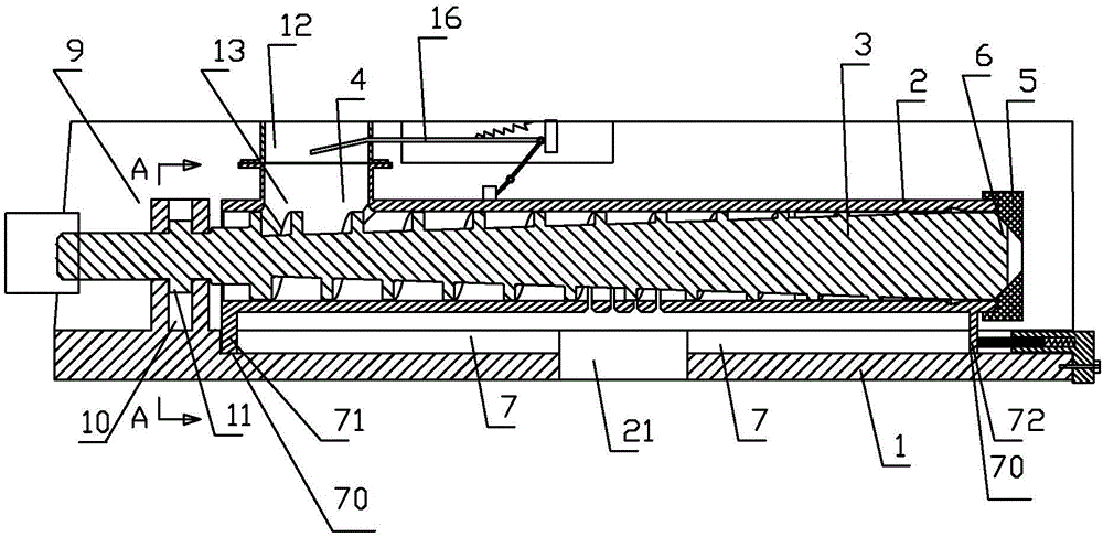
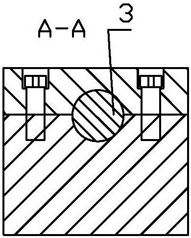
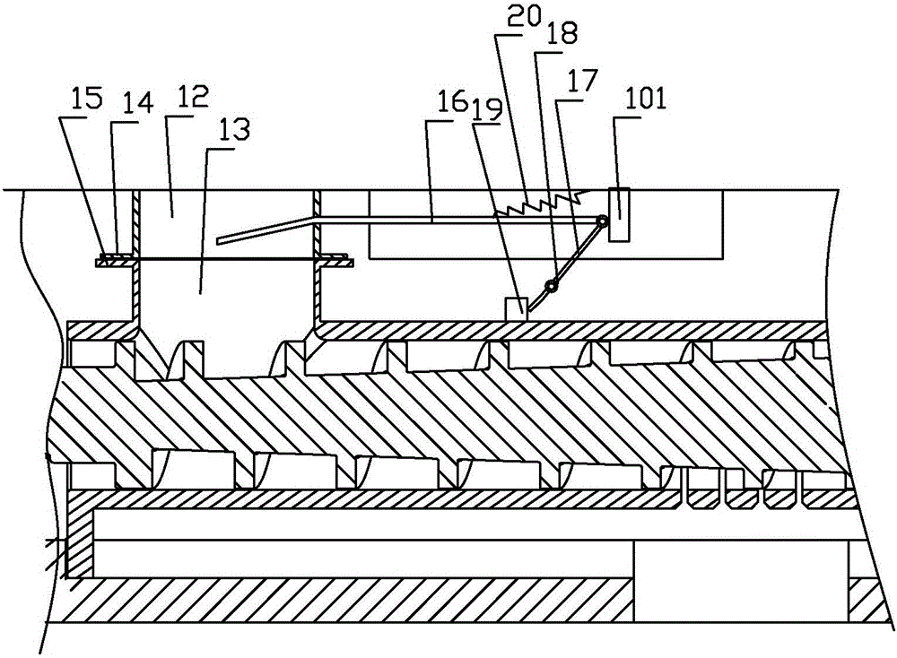
[0045] Embodiment 1: as Figure 1 to Figure 11 As shown, a movable oil press mechanism cleaning system includes a component seat 1, a press chamber 2, and a press rod 3, and the press rod 3 is located in the press chamber; the press chamber 2 includes a conveying material section and a pressing section; the conveying material section is provided with The feeding hole 4, the conveying section and the pressing section are arranged in sequence, the conveying section and the pressing section are integrally formed, and the conveying section and the pressing section are on the same axis; the end of the pressing section is detachably connected with a tail sleeve 5; The tail end of the platform is provided with a platform body section 6, the outer diameter of the platform body section 6 gradually becomes smaller in the axially outward direction, and the inner wall of the tail sleeve 5 matches the outer wall 60 of the platform body section 6. The movable oil pressing mechanism includes...


PUM


Abstract

The invention discloses a movable type cleaning system of an oil pressing mechanism. An upper loading barrel is connected with loading equipment; the upper loading barrel and a lower loading barrel can be mutually movable; a material control plate is inserted into the upper loading barrel; the outer end of the material control plate is hinged with one end of a rotary strip; the rotary strip can rotate around a rotary pin; a touch part is arranged on a pressing chamber; the setting position of the touch part corresponds to the other end of the rotary strip; and the movable type cleaning system further comprises a tension spring for returning the material control plate, and a cleaning auxiliary device, wherein the cleaning auxiliary device comprises a pedestal and a movable base hinged with the pedestal. Dynamic equilibrium is realized by moving the pressing chamber and regulating the material control plate to adapt to different working conditions, so that the material control plate is automatically regulated in a moving process of the pressing chamber, and therefore, oil of different sizes can be adapted. The cleaning auxiliary device is utilized, so that the pressing chamber and a pressing rod can be cleaned without independently detaching the pressing rod from the pressing chamber.

Description

technical field [0001] The invention relates to a cleaning system for a household movable oil press mechanism, which can be used for pressing various large and small oil plants such as peanuts, beans, and sesame seeds. Background technique [0002] In the prior art, the general press mechanism is composed of a press rod and a press chamber, and the rear end of the press chamber is detachably connected with a slag discharge sleeve; in order to solve the problem of oil production efficiency and slag discharge of different oil species, the press chamber can Select different slagging sleeves, for example, when pressing oil with large particles of peanuts, use the slagging sleeve with a large slagging tank; For granular oil, the oil will come out of the slag discharge tank without deep pressing, and it will not affect the pressing efficiency of the pressing mechanism. The disadvantage of this type of structure is: the operation of the pressing mechanism of this type of structure...

Claims


Application Information

Patent Timeline
IPC IPC(8): B30B9/14B30B15/00
CPCB30B9/14B30B15/00
Inventor 傅强
Owner 陈妙娟
Features
  • Generate Ideas
  • Intellectual Property
  • Life Sciences
  • Materials
  • Tech Scout
  • Unparalleled Data Quality
  • Higher Quality Content
  • 60% Fewer Hallucinations
Learn More