
Self-propelled trolley conveying line polling device

A self-propelled trolley and conveyor line technology, applied in conveyors, measuring devices, mechanical conveyors, etc., can solve the problems of high labor intensity of workers, slopes on the track, unsafe, etc., to improve working conditions, good inspection effects, The effect of low labor intensity

Active Publication Date: 2016-08-31
HUANGSHI HUATIAN AUTOMATION EQUIP
View PDF6 Cites 0 Cited by
  • Summary
  • Abstract
  • Description
  • Claims
  • Application Information

AI Technical Summary

Problems solved by technology

[0002] In the existing self-propelled trolley conveyor line, especially in the case of mine material transportation, in order to check whether there is a fault in the conveyor line and to understand the production environment in detail (such as: the concentration of dangerous gases such as gas, etc.), workers need to conduct inspections along the line one by one , but due to the harsh working environment and long conveying line, the track may have slope rails, curved rails, and caves, which is not safe, and the labor intensity of workers is also great. Missed detection due to fatigue

Method used


Image

  • Self-propelled trolley conveying line polling device
  • Self-propelled trolley conveying line polling device
  • Self-propelled trolley conveying line polling device

Examples


Embodiment Construction

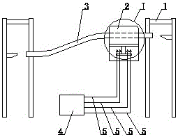
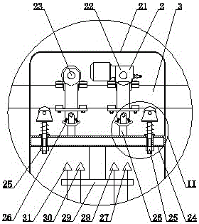
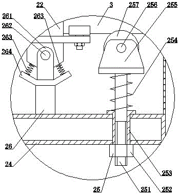
[0009] see Figure 1 to Figure 3 , the present invention includes an auxiliary beam 1 and a track 3, the track 3 is mounted on the auxiliary beam 1, and also includes an inspection trolley 2, and the inspection trolley 2 includes a transparent outer cover 21, a main vehicle 22, an auxiliary vehicle 23, an equalizing beam 24. Laser anti-collision sensor 27, temperature sensor 28, sensor support 29, combustible gas sensor 30, camera 31, control center 4, signal line 5, two equalizing beam stabilizing devices 25 and two car body stabilizing devices 26, all Described each equalizing beam stabilizing device 25 comprises guide rod 251, nut 252, guide sleeve 253, large compression spring 254, roller seat 255, roller rotating shaft 256 and roller 257, and described guide sleeve 253 is contained in the hole of equalizing beam 24, The roller 257 is installed on the roller seat 255 through the roller rotating shaft 256, the upper end of the guide rod 251 is welded on the bottom surface o...


PUM


Abstract

The invention discloses a self-propelled trolley conveying line polling device. The device comprises an auxiliary beam and a rail; and the rail is mounted on the auxiliary beam. The device is characterized by further comprising a polling trolley; the polling trolley includes a transparent cover, a main trolley, a secondary trolley, a balance beam, a laser anti-collision sensor, a temperature sensor, a sensor bracket, a combustible gas sensor, a camera, a control center, a signal wire, two balance beam stabilizing devices and two trolley body stabilizing devices; each balance beam stabilizing device includes a guide rod, a nut, a guide sleeve, a large compression spring, a roller base, a roller rotating shaft and a roller; the guide sleeve is mounted in a hole of the balance beam; the roller is mounted on the roller base through the roller rotating shaft; the upper end of the guide rod is welded on the bottom surface of the roller base; and the compression spring coats the guide rod, and is mounted between the bottom surface of the roller base and the upper end surface of the guide sleeve. The device is novel in structure, excellent in polling effect, safe, reliable, low in labor intensity and capable of prominently improving the labor conditions.

Description

technical field [0001] The invention relates to conveying equipment, in particular to a patrol inspection device for a self-propelled trolley conveying line. Background technique [0002] Currently, in the self-propelled trolley conveyor line, especially in the case of mine material transportation, in order to check whether there is a fault in the conveyor line and to understand the production environment in detail (such as: the concentration of dangerous gases such as gas, etc.), workers need to conduct inspections along the line one by one , but due to the harsh working environment and the long conveying line, the track may have slope rails, curved rails, and caves, which is not safe, and the labor intensity of the workers is also great. Missed detection due to fatigue. Contents of the invention [0003] The purpose of the present invention is to provide a self-propelled trolley conveyor line inspection device with novel structure, good inspection effect, safety and rel...

Claims


Application Information

Patent Timeline
IPC IPC(8): B65G35/00G01D21/02G01S17/93
CPCB65G35/00G01D21/02G01S17/93
Inventor 余启良
Owner HUANGSHI HUATIAN AUTOMATION EQUIP
Learn More