
Gas-liquid separator for oil field

A technology of gas-liquid separator and cyclone separator, which is applied in the chemical/physical/physical-chemical process of applying energy, wellbore/well components, production fluid, etc. Corrosion and other problems, to achieve the effect of improving the desorption rate, effective desorption, and accelerated desorption

Active Publication Date: 2018-12-21
CHINA UNIV OF PETROLEUM (BEIJING)
View PDF5 Cites 0 Cited by
  • Summary
  • Abstract
  • Description
  • Claims
  • Application Information

AI Technical Summary

Problems solved by technology

When CO 2 When gas channeling occurs in the middle and late stages of oil displacement, it will often cause CO 2 The gas content increases sharply. If a large amount of carbon dioxide gas and water in the produced liquid cannot be effectively separated, the corrosion of subsequent equipment will be aggravated
[0003] due to CO 2 Compared with conventional associated gas, the dissolution and desorption characteristics in the produced fluid are very different, so that the existing oil and gas separation methods (mainly including gravity separation, inertial separation, filtration separation, centrifugal separation and combinations of various methods) cannot Realize CO within the stipulated time 2 Efficient desorption of gases
[0004] The gas-liquid separator is the most widely used and most important gas-liquid separation equipment in oil and gas fields. 2 After gas channeling occurs in the oil flooding field, a large amount of CO will be dissolved in the produced fluid 2 For the problem of gas, at present, in the field production, the residence time of the produced liquid in the separator is only extended based on experience in order to achieve the ideal degree of desorption, but the effect is not obvious

Method used


Image

  • Gas-liquid separator for oil field
  • Gas-liquid separator for oil field

Examples


Embodiment Construction

[0023] The technical solutions of the present invention will be further described below in conjunction with the accompanying drawings and through specific implementation methods.

[0024] Preferred embodiment:

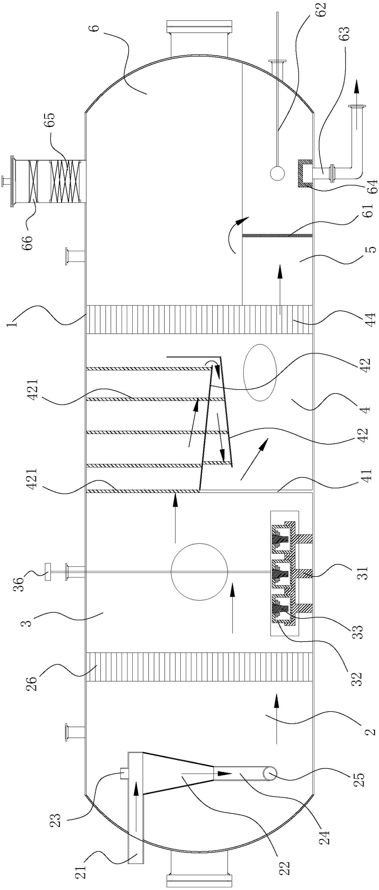
[0025] This preferred embodiment provides a gas-liquid separator for oilfields, the gas-liquid separator includes a housing 1, and an ultrasonic system is arranged in the housing 1, and the desorption of carbon dioxide gas in the production fluid is improved by the ultrasonic waves generated by the ultrasonic system rate, solves for CO 2 A large amount of CO dissolved in the produced fluid after gas channeling in the oil flooding field 2 The problem of gas not desorbing quickly.

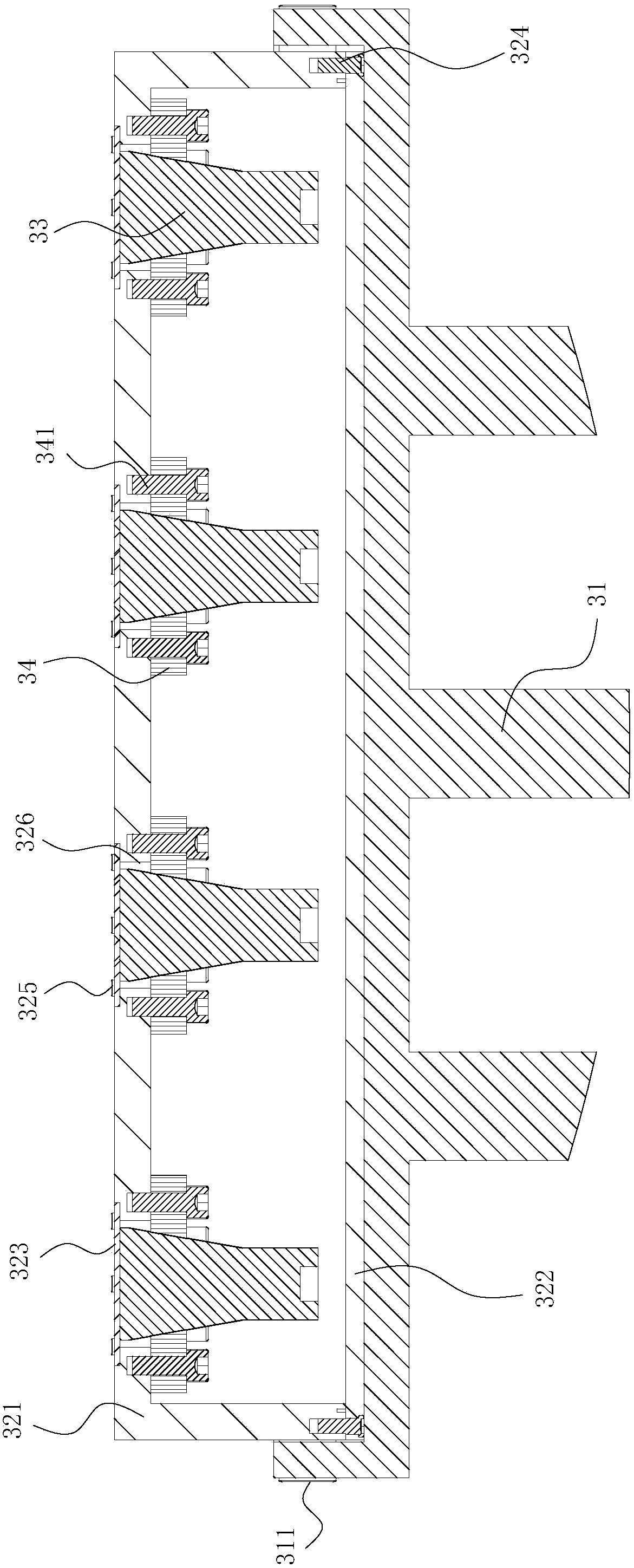
[0026] like figure 1 As shown, the preferred structure of the gas-liquid separator comprises a horizontal cross-section cylindrical housing 1, in which a primary separation chamber 2, a secondary separation chamber 3, a defoaming chamber 4, a settling chamber 5 and Oil chamber 6; the ultr...


PUM


Abstract

The invention discloses a gas-liquid separator for an oil field, and belongs to the technical field of gas-liquid separation of the oil field ground technology. The gas-liquid separator for the oil field is designed for solving the problem that after gas channeling occurs in a carbon dioxide flooding oil field, desorption of a large amount of carbon dioxide gas dissolved in produced liquid is difficult. The gas-liquid separator of the oil field comprises a shell, an ultrasonic system is arranged in the shell, and the ultrasonic system can generate ultrasonic waves so as to improve the desorption rate of carbon dioxide gas in the produced liquid. According to the gas-liquid separator of the oil field, the desorption rate of carbon dioxide gas in the produced liquid is improved through the cavatition effect and the mechanical effect of the ultrasonic waves, desorption of carbon dioxide gas in the produced liquid of the carbon dioxide flooding oil field is accelerated, carbon dioxide gas entering the produced liquid of the separator can be effectively desorbed within a standard set period, and the problem that desorption of carbon dioxide gas in the produced liquid of the carbon dioxide flooding oil field is difficult is solved.

Description

technical field [0001] The invention relates to the technical field of gas-liquid separation in oilfield surface technology, in particular to a gas-liquid separator for oilfields. Background technique [0002] Given CO 2 Oil flooding technology has many advantages, and this oil recovery technology has been widely promoted. When CO 2 When gas channeling occurs in the middle and late stages of oil displacement, it will often cause CO 2 The gas content increases sharply. If a large amount of carbon dioxide gas and water in the produced liquid cannot be effectively separated, the corrosion of subsequent equipment will be aggravated. [0003] due to CO 2 Compared with conventional associated gas, the dissolution and desorption characteristics in the produced fluid are very different, so that the existing oil and gas separation methods (mainly including gravity separation, inertial separation, filtration separation, centrifugal separation and combinations of various methods) c...

Claims


Application Information

Patent Timeline
Patent Type & Authority Patents(China)
IPC IPC(8): E21B43/34E21B43/16B01J19/10
CPCB01J19/10E21B43/164E21B43/34
Inventor 邢晓凯酆春博王少松程成卞胜乐
Owner CHINA UNIV OF PETROLEUM (BEIJING)
Learn More