Vacuum sealing joint for low-temperature tubular heating tube

A tubular heating tube and vacuum sealing technology, which is applied to engine sealing, engine components, mechanical equipment, etc., can solve the problems of increasing the cost of decompression equipment, high cost, and unrealistic, etc., and achieves simple structure, simple assembly, and obvious effect Effect

Inactive Publication Date: 2016-08-31
SHANGHAI HENGTUO HYDRAULIC CONTROL TECH
View PDF5 Cites 2 Cited by
  • Summary
  • Abstract
  • Description
  • Claims
  • Application Information

AI Technical Summary

Problems solved by technology

[0002] In the manufacture of low-temperature (less than 400°C) small-scale internal heating vacuum heating furnaces, in order to improve the temperature uniformity of the heated furnace, tubular heating tube heating elements can be used. However, the heating voltage in the vacuum furnace must be lower than 80 volts. Vacuum discharge does not occur, and the voltage step-down device is usually configured to reduce the voltage of 220 volts (or three-phase 380 volts) to below 80 volts. For example, a magnetic voltage regulator is configured, so that through the conventional vacuum electrical sealing joint configured on the vacuum furnace, The 80 volt voltage outside the furnace is connected to the outer contact point of the vacuum electrical joint, and the joint of the heating element in the furnace can be directly connected to the inner contact point of the vacuum electrical joint without vacuum discharge. Using a 220-volt tubular heating tube as a heating element to make a small low-temperature vacuum heating furnace is unrealistic due to the high cost

Method used


Image

  • Vacuum sealing joint for low-temperature tubular heating tube
  • Vacuum sealing joint for low-temperature tubular heating tube
  • Vacuum sealing joint for low-temperature tubular heating tube

Examples


Embodiment Construction

[0016] The present invention will be further explained below in conjunction with the accompanying drawings.

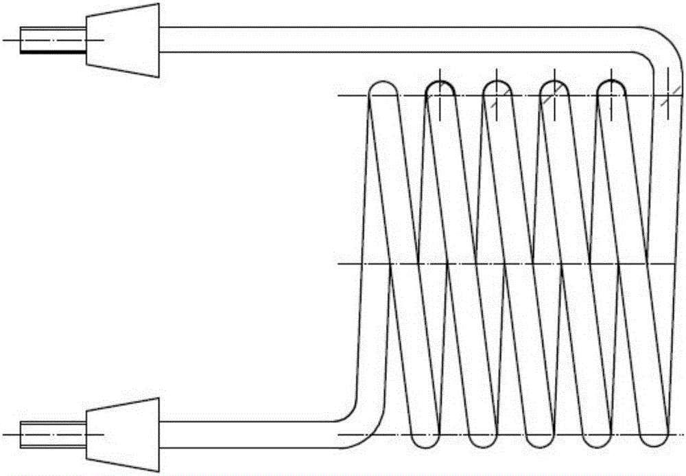
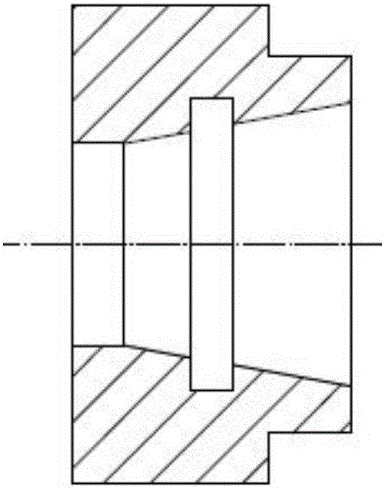
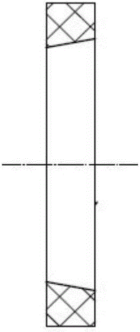
[0017] Such as Figure 1 to Figure 5 As shown, the low-temperature tubular heating tube vacuum sealing joint of the present invention includes a tubular spiral heating tube 201 , a vacuum joint 203 , a sealing ring 204 , and a compression nut 205 . Vacuum furnace wall 202 pre-machines the hole for installing vacuum joint 203. The vacuum joint is inserted into the hole from the outside of the furnace and welded on the vacuum furnace wall. The direction of the cone is the same. Insert the two conductive ends of the tubular spiral heating tube 201 into the vacuum joint from the furnace. 205 respectively screw on the two conductive ends of the tubular spiral heating tube 201, and tighten to make the tapered part of the tubular spiral heating tube compress the sealing ring 204 to achieve the vacuum sealing effect, screw on the other two compression nuts 205 and tighten the...


PUM


Abstract

The invention relates to a vacuum sealing joint for a low-temperature tubular heating tube. The vacuum sealing joint comprises a tubular spiral heating tube, a vacuum joint, a sealing ring and compression nuts, wherein the vacuum joint is fixedly connected into an installation hole of a vacuum furnace wall; conducting ends of the tubular spiral heating tube are inserted in the vacuum joint; the vacuum joint is provided with inner conical holes, and in fit connection with outer conical tables on the tubular spiral heating tube through the inner conical holes; the sealing ring is arranged between the inner conical holes and the outer conical tables; and the tubular spiral heating tube is locked and fixed, and the sealing ring is compressed on the conducting ends of the tubular spiral heating tube through the compression nuts, so as to achieve a vacuum sealing effect. The joint enables a heating component of a vacuum furnace to be directly supplied with power of 220 V instead of being supplied with power by configuring voltage dropping equipment, thus configuration of a small vacuum furnace is simplified, and the equipment cost is reduced. Moreover, a reliable sealing structure is provided for producing the small vacuum heating furnace by virtue of the heating component for vacuum heating, and a technical support is provided for producing the small vacuum heating furnace by widely using the tubular heating tube.

Description

technical field [0001] The invention relates to a vacuum sealing joint for a low-temperature (less than 400°C) vacuum heating furnace, in particular to a vacuum sealing joint for a tubular heating tube of a vacuum heating furnace. Background technique [0002] In the manufacture of low-temperature (less than 400°C) small-scale internal heating vacuum heating furnaces, in order to improve the temperature uniformity of the heated furnace, tubular heating tube heating elements can be used. However, the heating voltage in the vacuum furnace must be lower than 80 volts. Vacuum discharge does not occur, and the voltage step-down device is usually configured to reduce the voltage of 220 volts (or three-phase 380 volts) to below 80 volts. For example, a magnetic voltage regulator is configured, so that through the conventional vacuum electrical sealing joint configured on the vacuum furnace, The 80 volt voltage outside the furnace is connected to the outer contact point of the vac...

Claims


Application Information

Patent Timeline
Patent Type & Authority Applications(China)
IPC IPC(8): F16J15/06
CPCF16J15/06
Inventor 田书明张宪程雪飞缑楠楠苏二锐
Owner SHANGHAI HENGTUO HYDRAULIC CONTROL TECH
Why Eureka
Try Eureka