Oil injector of oil-fired heating furnace

A fuel injector and heating furnace technology, which is used in burners, liquid fuel burners, lighting and heating equipment, etc., can solve problems such as poor atomization effect, easy burnout of the burner, loss and other problems

Inactive Publication Date: 2016-08-31
史亮
View PDF12 Cites 0 Cited by
  • Summary
  • Abstract
  • Description
  • Claims
  • Application Information

AI Technical Summary

Problems solved by technology

[0002] At present, the fuel injectors used in heating furnaces on the market include pressure injectors, oil return injectors, rotary cup injectors, etc. During use, the injectors are installed on the furnace wall of the heating furnace , the nozzle part of the fuel injector is exposed to the inner wall of the heating furnace. Due to the special working environment (high temperature) of the heating furnace, the control valves and other control equipment that control the start and stop of the fuel injector are installed outside the furnace wall of the heating furnace. On the outside of the wall, after the injector stops spraying, there is still a lot of fuel in the fuel injection channel of the injector, and the fuel will continue to burn until it is completely burned. Continue to inject fuel, and the atomization effect is prone to be poor. If the fuel injector starts and stops frequently, the nozzle of the fuel injector will always be in a burning state, and the control will lose its effect, and it is easy to burn the burner

Method used


Image

  • Oil injector of oil-fired heating furnace
  • Oil injector of oil-fired heating furnace
  • Oil injector of oil-fired heating furnace

Examples


Embodiment Construction

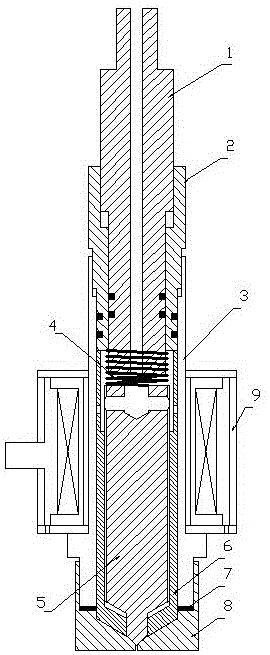
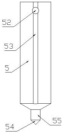
[0027] The present invention will be further described in detail below in conjunction with the examples: the present invention is a fuel injector used on a heating furnace, which is different from ordinary injectors. The cut-off control is at the nozzle, which can significantly increase the control frequency of the injector. The fuel injection path of the fuel injector adopts a tangential direction at the end to form a swirl spray, and the atomization effect is good.

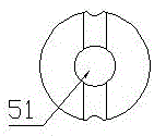
[0028] like Figure 1-11 As shown, the main body of the fuel injector of the present invention consists of a fuel injector housing 1, a nozzle 8 installed on the front end of the fuel injector housing 1, a plunger sleeve 6 installed in the fuel injector housing 1, a plunger 5, a reset Spring 4, the plunger sleeve mounted on the rear end of the injector housing 1 tightens the fixed sleeve 2, the plunger adjustment rod 1 installed in the plunger sleeve tightens the fixed sleeve 2, and is set on the injector housin...


PUM

PropertyMeasurementUnit
Cone angleaaaaaaaaaa

Abstract

The invention discloses an oil injector of an oil-fired heating furnace and belongs to the technical field of oil injectors. The oil injector comprises a nozzle, an oil injector shell, a plunger sleeve, a plunger, a reset spring, a plunger sleeve abutting and fixing sleeve, a plunger adjusting rod, an electromagnetic coil and an electromagnetic coil shell. The plunger, the electromagnetic coil and the electromagnetic coil shell form an electromagnet, the plunger serves as an armature of the formed electromagnet and is installed in the plunger sleeve, the reset spring is located between the rear end of the plunger and the plunger adjusting rod, and an oil passing hole of the plunger adjusting rod, a vertical blind hole and a horizontal oil passing hole in the tail end of the plunger, a through hole in the tail end of the plunger sleeve, an oil groove in the outer wall of the plunger sleeve and an oil injection hole in the nozzle form an oil flowing and injection path. Swirl oil injection is achieved by means of the oil groove in the outer side wall of the plunger sleeve, and the atomizing effect is good; the plunger is controlled by the electromagnetic coil to move, and control over the oil injection state of the oil injector is achieved; when oil injection stops, an injection hole of the nozzle can be closed, instant oil cutoff is achieved, oil amount is precisely controlled, and the high-precision control requirements are met.

Description

technical field [0001] The invention belongs to the technical field of fuel injectors, and in particular relates to a fuel injector for a fuel heating furnace. Background technique [0002] At present, the fuel injectors used in heating furnaces on the market include pressure injectors, oil return injectors, rotary cup injectors, etc. During use, the injectors are installed on the furnace wall of the heating furnace , the nozzle part of the fuel injector is exposed to the inner wall of the heating furnace. Due to the special working environment (high temperature) of the heating furnace, the control valves and other control equipment that control the start and stop of the fuel injector are installed outside the furnace wall of the heating furnace. Since the control valve is located on the furnace wall On the outside of the wall, after the injector stops spraying, there is still a lot of fuel in the fuel injection channel of the injector, and the fuel will continue to burn unt...

Claims


Application Information

Patent Timeline
IPC IPC(8): F23D11/38F23D11/36F23D11/26
CPCF23D11/26F23D11/36F23D11/383F23D2202/00
Inventor 史亮崔长在
Owner 史亮
Why Eureka
Try Eureka