
Screw fine-debugging mechanism of dynamic balance test bench for rigid rotor

A technology of rigid rotors and experimental benches, applied in the field of experimental equipment, can solve the problems of long time consumption, limited time for students, and low debugging accuracy, and achieve the effect of convenient dynamic balance adjustment and low manufacturing cost

Inactive Publication Date: 2016-08-31
YANCHENG INST OF TECH
View PDF6 Cites 9 Cited by
  • Summary
  • Abstract
  • Description
  • Claims
  • Application Information

AI Technical Summary

Problems solved by technology

In the process of adjusting the balance of the above-mentioned unbalanced quantity, the key lies in the rapid adjustment of the unbalanced quantity on the rigid rotor. However, in the debugging process of the existing dynamic balance test bench, firstly start the machine and run it to find out the position and angular direction of the unbalanced mass, and then Add mass blocks of different specifications on the end face of the rigid rotor, turn on the machine again, and add mass blocks of different specifications at the new unbalanced position. Repeatedly, it needs multiple adjustments to achieve dynamic balance.
Therefore, the above debugging method has the disadvantages of long time-consuming repeated debugging and low debugging accuracy
The dynamic balance experiment project in ordinary colleges and universities is 2 credit hours. Excluding the time for the teacher to explain the experiment, the time for students to actually practice and debug is very limited. If there is no accurate and fast balance adjustment method when debugging the dynamic balance test bench, repeated debugging is required. , will cause many students to fail to complete the experimental project within a limited time

Method used


Image

  • Screw fine-debugging mechanism of dynamic balance test bench for rigid rotor
  • Screw fine-debugging mechanism of dynamic balance test bench for rigid rotor
  • Screw fine-debugging mechanism of dynamic balance test bench for rigid rotor

Examples


Embodiment Construction

[0032] In order to make the purpose, technical solutions and advantages of the embodiments of the present invention clearer, the technical solutions in the embodiments of the present invention will be clearly and completely described below in conjunction with the drawings in the embodiments of the present invention. Obviously, the described embodiments It is a part of embodiments of the present invention, but not all embodiments. The components of the embodiments of the invention generally described and illustrated in the figures herein may be arranged and designed in a variety of different configurations.

[0033] Accordingly, the following detailed description of the embodiments of the invention provided in the accompanying drawings is not intended to limit the scope of the claimed invention, but merely represents selected embodiments of the invention. Based on the embodiments of the present invention, all other embodiments obtained by persons of ordinary skill in the art wi...


PUM


Abstract

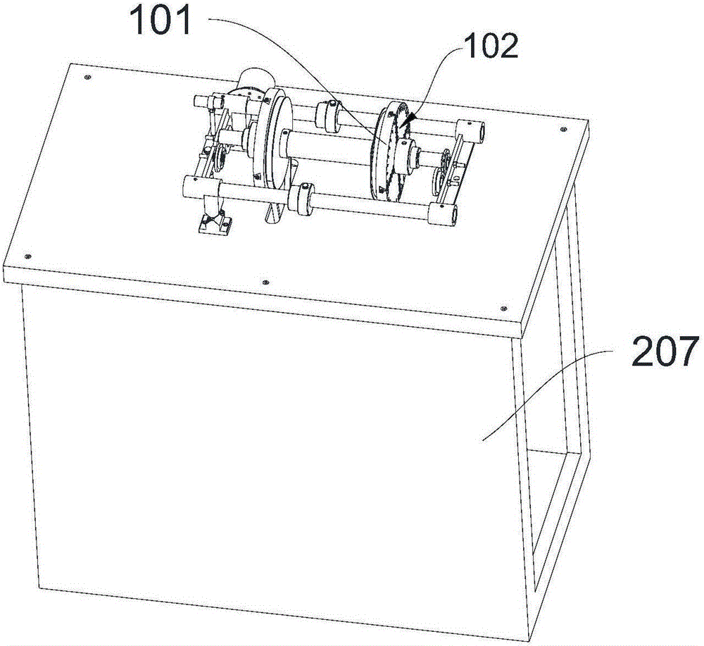
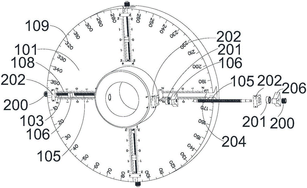
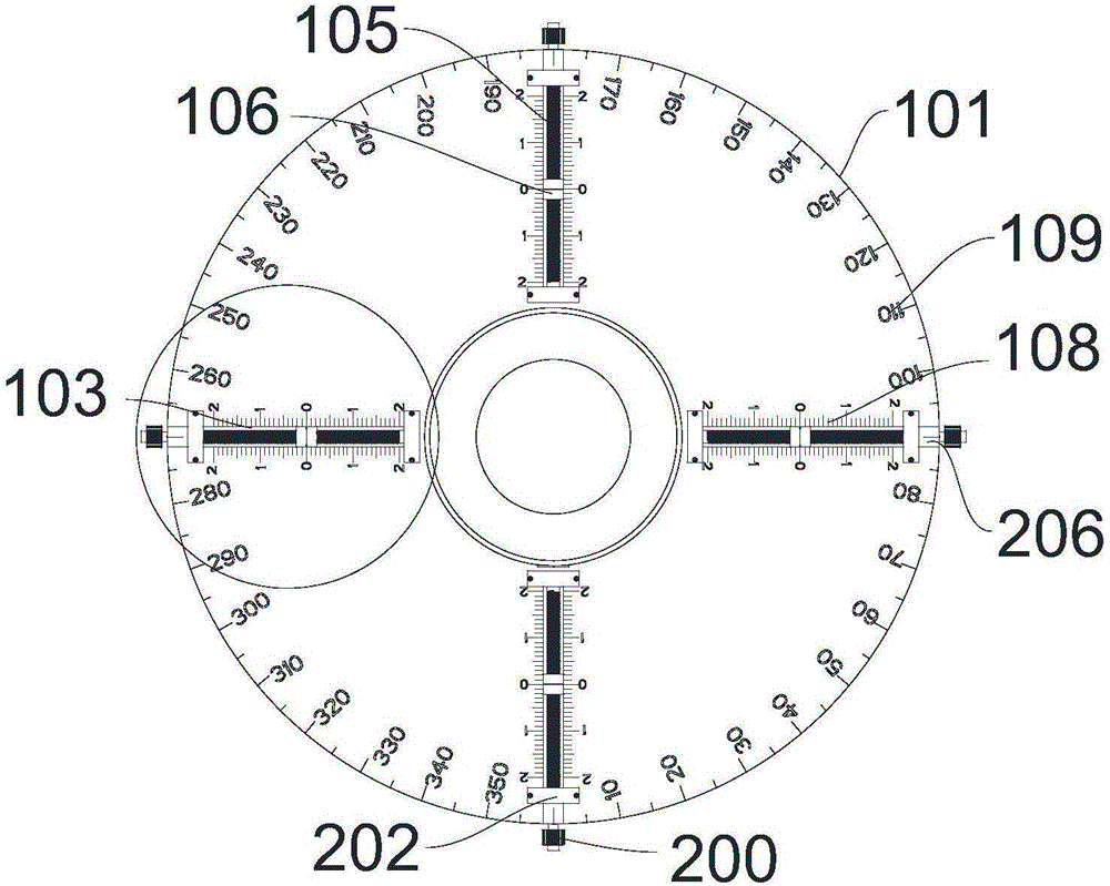
The invention provides a screw fine-debugging mechanism of a dynamic balance test bench for a rigid rotor, and belongs to the field of experiment instruments. The screw fine-debugging mechanism comprises a rigid rotor and a debugging assembly, wherein four radial slide chutes are formed in the end surface of the rigid rotor and are evenly arranged at intervals along the circumferential direction of the rigid rotor; the motion direction defined by the four radial slide chutes is along the radial direction of the rigid rotor; one debugging assembly is arranged in each radial slide chute and comprises a fine-debugging screw rod, a balance mass block and a fine-debugging part; each fine-debugging screw rod passes through the corresponding balance mass block and is in threaded connection with the corresponding balance mass block; each fine-debugging screw rod is rotatably arranged in the corresponding radial slide chute; each balance mass block is slidably embedded into the corresponding radial slide chute; each fine-debugging part is arranged at one end, far away from the rigid rotor, of the corresponding fine-debugging screw rod; each fine-debugging part is used for driving the corresponding fine-debugging screw rod to rotate. According to the technical scheme, balance is achieved through adjusting the radial positions of the balance mass blocks; the balance mass blocks can be quickly adjusted; fast dynamic balance is achieved.

Description

technical field [0001] The invention relates to the field of experimental equipment, in particular to a helical micro-adjustment mechanism of a rigid rotor dynamic balance experiment platform. Background technique [0002] The dynamic balance test bench is a machine used to test the size and phase of the unbalance of the rigid rotor (rotating parts), and then perform balance adjustment. Throughout the rotating mechanism, no vibration is unique, and according to production experience, most of the unbalance is due to the inertial force caused by the unbalanced mass, which causes the vibration to cause the unbalance, and the high-precision rotor system installed correctly under certain conditions is also Vibration will be generated due to wear and load impact during long-term rotation, especially for high-speed rotary machines, during the initial run-in period and long-term work, there will be large vibrations, which will cause the machine to not work normally and cause huge ec...

Claims


Application Information

Patent Timeline
Patent Type & Authority Applications(China)
IPC IPC(8): G01M1/02G01M1/38
CPCG01M1/02G01M1/30
Inventor 赵世田付莹莹郁倩袁健崔治卢倩张波
Owner YANCHENG INST OF TECH
Learn More