
Cuvette top-driven pushing apparatus

A technology for pushing devices and cuvettes, applied in measuring devices, material analysis through optical means, instruments, etc., can solve problems such as differences in test results, and achieve the effects of convenient replacement, simple detection and operation, and cost savings

Inactive Publication Date: 2016-08-31
CHENGDU EMPEROR MEDICAL TECH CO LTD
View PDF0 Cites 0 Cited by
  • Summary
  • Abstract
  • Description
  • Claims
  • Application Information

AI Technical Summary

Problems solved by technology

[0005] The purpose of the present invention is to solve the problem that a very small displacement deviation in the prior art will also lead to large differences in detection results, and a structure that can effectively improve the movement accuracy of the cuvette is needed; provide a simple structure that can effectively improve the ratio Cuvette top-driven pusher for cuvette movement precision

Method used


Image

  • Cuvette top-driven pushing apparatus
  • Cuvette top-driven pushing apparatus

Examples


Embodiment

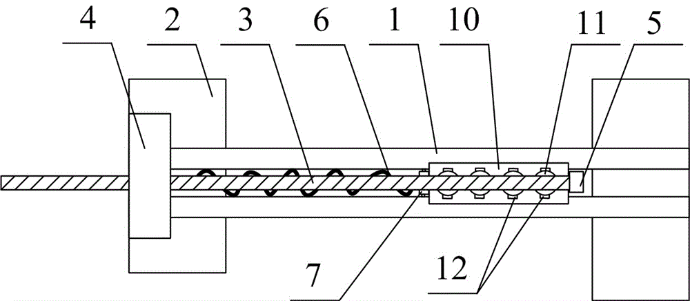
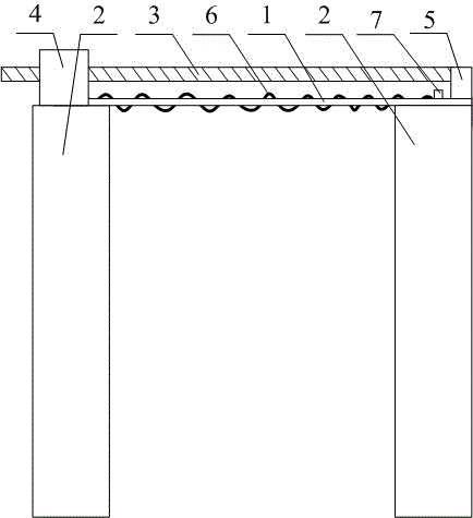
[0025] Cuvette top-driven pusher such as figure 1 and figure 2 As shown, it includes two specimen placement rods 1 that are parallel to each other and form a cuvette moving channel between them, a base 2 that is arranged below the specimen placement rod 1 , and a base 2 that is parallel to the specimen placement rod 1 and located above the specimen placement rod 1 A ball screw 3, a driving mechanism 4 arranged at one end of the ball screw 3, and a sample moving part 5 arranged at the other end of the ball screw 3;

[0026] The driving mechanism 4 is a motor that drives the ball screw 3, and the motor drives the ball screw 3 to convert the rotary motion of the ball screw 3 into a linear motion.

[0027] A spring 6 parallel to the two specimen placement rods 1 is arranged, and the end of the spring 6 adjacent to one end of the specimen moving part 5 is provided with a baffle 7 , and the other end of the spring 6 is fixed on the base 2 , And the two ends of the baffle plate 7 ...


PUM


Abstract

A cuvette top-driven pushing apparatus disclosed in the invention belongs to the field of semiautomatic biochemical analyzers, and mainly solves the problem of a structure for effectively improving the movement accuracy of a cuvette, needed in the prior art due to an extremely small displacement deviation may induce a large detection result difference. The apparatus comprises two mutually-paralleling sample placing rods forming a movement channel, a pedestal arranged under the sample placing rods, a ball screw paralleling to the sample placing rods and positioned above the sample placing rods, a driving mechanism arranged at one end of the ball screw, and a sample moving piece arranged at the other end of the ball screw; and the ball screw preferably selects a ball screw, and the driving mechanism is a motor driving the ball screw to convert rotary motion into linear motion. The apparatus has the advantages of simple structure, and effective improvement of the movement accuracy of cuvettes.

Description

technical field [0001] The invention relates to a pushing structure, in particular to a cuvette top-driven pushing device. Background technique [0002] Photoelectric colorimetry, as one of the most commonly used detection methods in clinical medical testing and analysis, has been widely used in a variety of medical analysis instruments, such as biochemical analyzers, microplate readers, enzyme immunoassay analyzers and hemagglutination. The semi-automatic biochemical analyzer is a medical clinical instrument that measures the content of various components in human blood and urine, quantitative biochemical analysis results, and provides reliable digital evidence for clinical diagnosis of various diseases in patients. It is a necessary routine testing equipment for clinical practice. [0003] In the existing semi-automatic biochemical analyzer, there is a structure in which the cuvette moves linearly to the position of the light source for detection. After the sample to be te...

Claims


Application Information

Patent Timeline
Patent Type & Authority Applications(China)
IPC IPC(8): G01N21/13
CPCG01N21/13
Inventor 蒋萍
Owner CHENGDU EMPEROR MEDICAL TECH CO LTD
Learn More