Automobile insulation resistance detection circuit and method

A technology of insulation resistance and detection circuit, which is applied in the direction of measuring resistance/reactance/impedance, high resistance measurement, and measuring devices, etc. It can solve the problems of uncertain insulation detection cycle, long stabilization time, and affecting the accuracy of insulation resistance acquisition, etc.

Active Publication Date: 2016-08-31
GAC AION NEW ENERGY AUTOMOBILE CO LTD
View PDF4 Cites 41 Cited by
  • Summary
  • Abstract
  • Description
  • Claims
  • Application Information

AI Technical Summary

Problems solved by technology
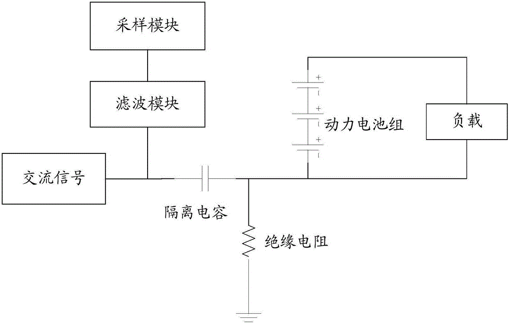
The time to stabilize is related to the insulation resistance Rn and Rp. When the insulation resistance is larger, the time to stabilize is longer, resulting in the uncertainty of the insulation detection cycle.
Inappropriate selection of R0 resistance, or when the switch is switched, the voltage collected when Vn and Vp are not stable will affect the collection accuracy of insulation resistance

Method used


Image

  • Automobile insulation resistance detection circuit and method
  • Automobile insulation resistance detection circuit and method
  • Automobile insulation resistance detection circuit and method

Examples


Embodiment 1

[0041] Embodiment 1 of the present invention provides an automobile insulation resistance detection circuit, Figure 6 It is the automobile insulation resistance detecting circuit diagram of embodiment one of the present invention, as Figure 6 As shown, the automobile insulation resistance detection circuit includes: negative discharge resistor R5, positive discharge resistor R6, first sampling resistor R1, second sampling resistor R2, third sampling resistor R3, fourth sampling resistor R4, fifth sampling resistor R7, sixth sampling resistor R8, negative switch Sn, positive switch Sp;

[0042] One end of the negative discharge resistor R5 is connected to the negative pole of the battery under test of the car, the other end of the negative discharge resistor R5 is grounded, one end of the positive discharge resistor R6 is connected to the positive pole of the battery under test, and the other end of the positive discharge resistor R6 is grounded;

[0043]One end of the first...

Embodiment 2

[0052] Embodiment 2 of the present invention provides an automobile insulation resistance detection circuit, Figure 8 It is the automobile insulation resistance detection circuit diagram of the second embodiment of the present invention, which shows a schematic diagram of the circuit structure of a preferred example of the automobile insulation resistance detection circuit of the present invention. The detection circuit can contain Figure 8 All shown in , may also include the part involved in Embodiment 1 and Figure 8 One of the parts shown in except the part involved in the first embodiment.

[0053] Such as Figure 8 As shown, the automobile insulation resistance detection circuit in the second embodiment can also include a microcontroller 101 on the basis of the first embodiment, and the microcontroller 101 is used to control the on-off of the negative switch Sn and the positive switch Sp, so as to The automatic control of the negative switch Sn and the positive switc...

Embodiment 3

[0064] Embodiment 3 of the present invention provides an insulation resistance detection method based on the automobile insulation resistance detection circuit in any one of the above embodiments. see Figure 9 As shown, it is a schematic flow chart of the implementation of the insulation resistance detection method according to the third embodiment of the present invention. Such as Figure 9 As shown, the insulation resistance detection method of the third embodiment includes the following steps:

[0065] Step S201: closing the negative pole switch and the positive pole switch to obtain the first negative pole-to-ground voltage value and the first positive pole-to-ground voltage value;

[0066] Step S202: Determine whether the first negative pole-to-ground voltage value is greater than the first positive pole-to-ground voltage value, if yes, go to step S203, if not, go to step S205;

[0067] Step S203: Turn off the negative pole switch, and acquire the second positive pole...


PUM


Abstract

The invention relates to an automobile insulation resistance detection circuit and method, and the circuit comprises a negative bleeder resistor, a positive bleeder resistor, a first sampling resistor, a second sampling resistor, a third sampling resistor, a fourth sampling resistor, a fifth sampling resistor, a sixth sampling resistor, a negative switch, and a positive switch. One end of the negative bleeder resistor is connected with the negative electrode of a detected battery, and the other end of the negative bleeder resistor is grounded. One end of the positive bleeder resistor is connected with the positive electrode of the detected battery, and the other end is grounded. One end of the first sampling resistor is connected with the negative electrode, and the other end of the sampling resistor is connected with one end of the negative switch. The other end of the negative switch is connected with one end of the second sampling resistor, and the other end of the second sampling resistor is grounded. One end of the third sampling resistor is connected with the positive electrode, and the other end of the third sampling resistor is connected with one end of the positive switch. The other end of the positive switch is connected with one end of the fourth sampling resistor, and the other end of the fourth sampling resistor is grounded. One end of the fifth sampling resistor is connected with the positive electrode, and the other end of the fifth sampling resistor is connected with one end of the sixth sampling resistor. The other end of the sixth sampling resistor is connected with the negative electrode. According to the scheme of the invention, the circuit can improve the detection precision of insulation resistance.

Description

technical field [0001] The invention relates to the technical field of electric vehicles, in particular to an automobile insulation resistance detection circuit and an insulation resistance detection method thereof. Background technique [0002] Automobile insulation resistance detection is to detect the insulation resistance of the power battery of electric vehicles. It is an important function to ensure the insulation safety of electric vehicles. Its performance is directly related to the life safety of passengers. The detection methods used by each automobile manufacturer are different, and the accuracy of insulation resistance detection is also different. The traditional methods used in electric vehicle insulation resistance detection mainly include AC injection method and DC detection method (national standard method). [0003] However, due to the equivalent Y capacitance between the positive and negative poles of the battery and the vehicle body, both the traditional ...

Claims


Application Information

Patent Timeline
Patent Type & Authority Applications(China)
IPC IPC(8): G01R27/02
CPCG01R27/025
Inventor 赖吉健苏伟坤张宗煜蒋伟曾建宏
Owner GAC AION NEW ENERGY AUTOMOBILE CO LTD
Why Eureka
Try Eureka