Camera self-rotating 3D measurement and information acquisition device

A technology of acquisition device and rotating shaft device, which is applied in the direction of measuring device, optical device, diagnostic recording/measurement, etc., can solve the problems of no acquisition/measurement equipment and methods, reduce the volume and complexity of equipment, simplify calibration, Effect of space-saving structure

Active Publication Date: 2019-01-15
天目爱视(北京)科技有限公司
View PDF7 Cites 19 Cited by
  • Summary
  • Abstract
  • Description
  • Claims
  • Application Information

AI Technical Summary

Problems solved by technology

At present, there is no existing technology aware of the special requirements of this type of target acquisition, that is, there is no motivation t

Method used


Image

  • Camera self-rotating 3D measurement and information acquisition device
  • Camera self-rotating 3D measurement and information acquisition device
  • Camera self-rotating 3D measurement and information acquisition device

Examples


Example Embodiment

[0057] Example 1

[0058]The small-range, small-depth target object 3 has a smaller horizontal size compared with the camera acquisition range, and a smaller size along the depth direction of the camera, that is, the target object 3 has less information in the depth direction. In this application, although a single-camera system that moves in a large range through rails, robotic arms, etc. can also collect multi-angle images of the target object 3 to synthesize 3D point clouds or images, but these devices are more complicated, which reduces reliability. . And large movements lead to extended acquisition times. And because of its large size, it cannot be applied to many occasions (such as access control systems).

[0059] The small-scale and small-depth target 3 has its own unique characteristics, which require the acquisition / measurement equipment to be small in size, high in reliability, and fast in acquisition speed, especially its requirements for the acquisition range ...

Example Embodiment

[0068] Example 2

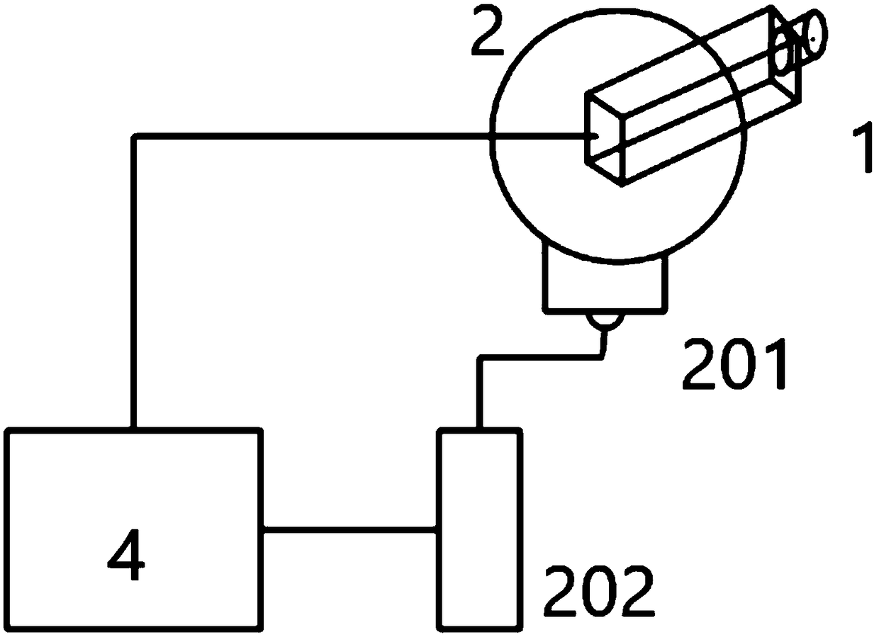
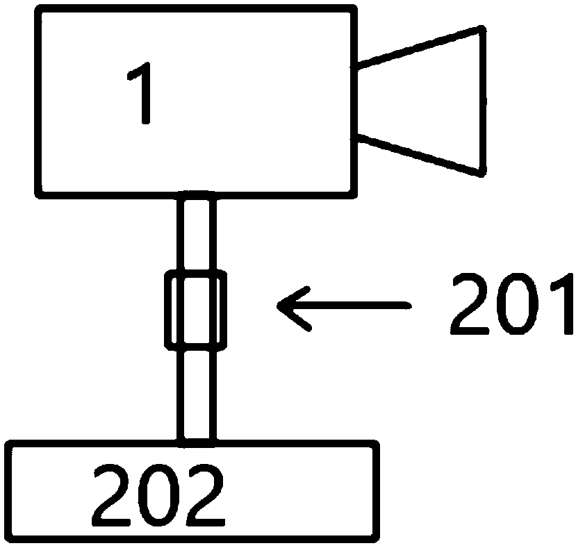
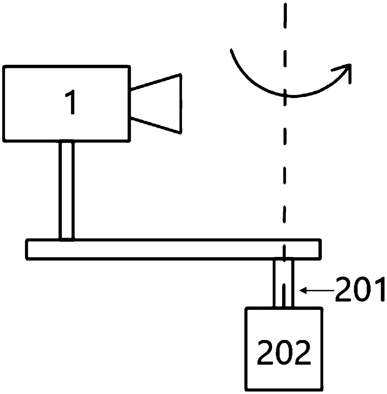
[0069] see image 3 -4. The 3D information acquisition device includes: an image acquisition device 1, which is used to collect a group of images of the target object 3 through the relative movement between the acquisition area of ​​the image acquisition device 1 and the target object 3; the acquisition area moving device 2, which is used to drive image acquisition The acquisition area of ​​the device 1 and the target object 3 produce relative motion; the acquisition area moving device 2 is an optical scanning device, so that when the image acquisition device 1 does not move or rotate, the acquisition area of ​​the image acquisition device 1 and the target object 3 produce relative motion .

[0070] see image 3 The acquisition area moving device 2 also includes a light deflection unit 211. Optionally, the light deflection unit 211 is driven by a light deflection drive unit 212. The image acquisition device 1 is a camera, and the camera is fixedly instal...


PUM


Abstract

The invention belongs to the technical field of 3D measurement, and provides a 3D information measurement device. The device comprises an image acquisition device, which is used for acquiring a groupof images of a target object through the relative movement of the acquisition area of the image acquisition device and the target object. A collection area moving device for driving the collection area of the image collecting device to generate relative motion with the target object; The acquisition area moving device adopts one of the following two schemes: 1) the acquisition area moving device is a rotating shaft device, so that the image collecting device rotates along a central axis; 2) that acquisition area move device is an optical scanning device, and under the condition that the imageacquisition device does not move or rotate, the acquisition area of the image acquisition device and the target object generate relative motion. The invention adopts a monocular camera and a mobile device of a collection area which is more simplified in structure and occupies less space. The fast conversion of the relative position between the acquisition area and the object is realized, the imageacquisition efficiency is accelerated, and the interference generated by the moving camera is reduced.

Description

technical field [0001] The invention relates to the technical field of 3D size measurement, in particular to the technical field of using pictures to perform 3D acquisition of objects to measure size and length. Background technique [0002] At present, with the continuous improvement of the requirements for 3D acquisition and measurement technology of the measured object in technologies such as medical treatment, security, biology, and parts manufacturing, visual measurement has many advantages such as good real-time performance in 3D acquisition. At present, many 3D acquisition and measurement equipment are mainly aimed at collecting a certain part of a person or a person, an object or a certain part of an object. For example, existing 3D equipment is used to collect 3D information on the face, or to collect Part 3D information collection. The well-known visual measurement technologies include monocular measurement and multi-eye measurement. Compared with multi-eye measur...

Claims


Application Information

Patent Timeline
IPC IPC(8): H04N13/20H04N13/204H04N13/156H04N5/232G01B11/00G01B11/02G01B11/24G01B11/28
CPCG01B11/24A61B5/1079A61B5/1176G06T3/4038G06V40/168G06V10/56
Inventor 左忠斌左达宇
Owner 天目爱视(北京)科技有限公司
Why Eureka
Try Eureka