
Calibration device and calibration method for infrared camera vision system

A technology of infrared camera and vision system, which is applied in the field of calibration device of infrared camera vision system, can solve problems such as inability to calibrate the camera, and achieve the effects of low cost, high detection efficiency and simple operation

Active Publication Date: 2018-11-16
GEER TECH CO LTD
View PDF5 Cites 0 Cited by
  • Summary
  • Abstract
  • Description
  • Claims
  • Application Information

AI Technical Summary

Problems solved by technology

[0003] The purpose of the present invention is to provide a calibration device for an infrared camera vision system, aiming to solve the problem that the infrared camera cannot use ordinary film charts or optical glass charts to calibrate the camera in the prior art

Method used


Image

  • Calibration device and calibration method for infrared camera vision system
  • Calibration device and calibration method for infrared camera vision system
  • Calibration device and calibration method for infrared camera vision system

Examples


Embodiment Construction

[0035] In order to make the object, technical solution and advantages of the present invention clearer, the present invention will be further described in detail below in conjunction with the accompanying drawings and embodiments. It should be understood that the specific embodiments described here are only used to explain the present invention, not to limit the present invention.

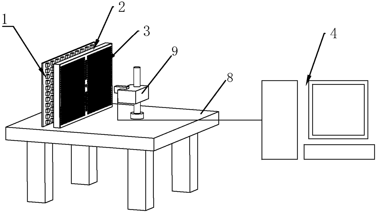
[0036] figure 1 A schematic structural diagram of the calibration device of the infrared camera vision system provided by the present invention is shown. For the convenience of description, only the parts related to the present invention are shown in the figure.

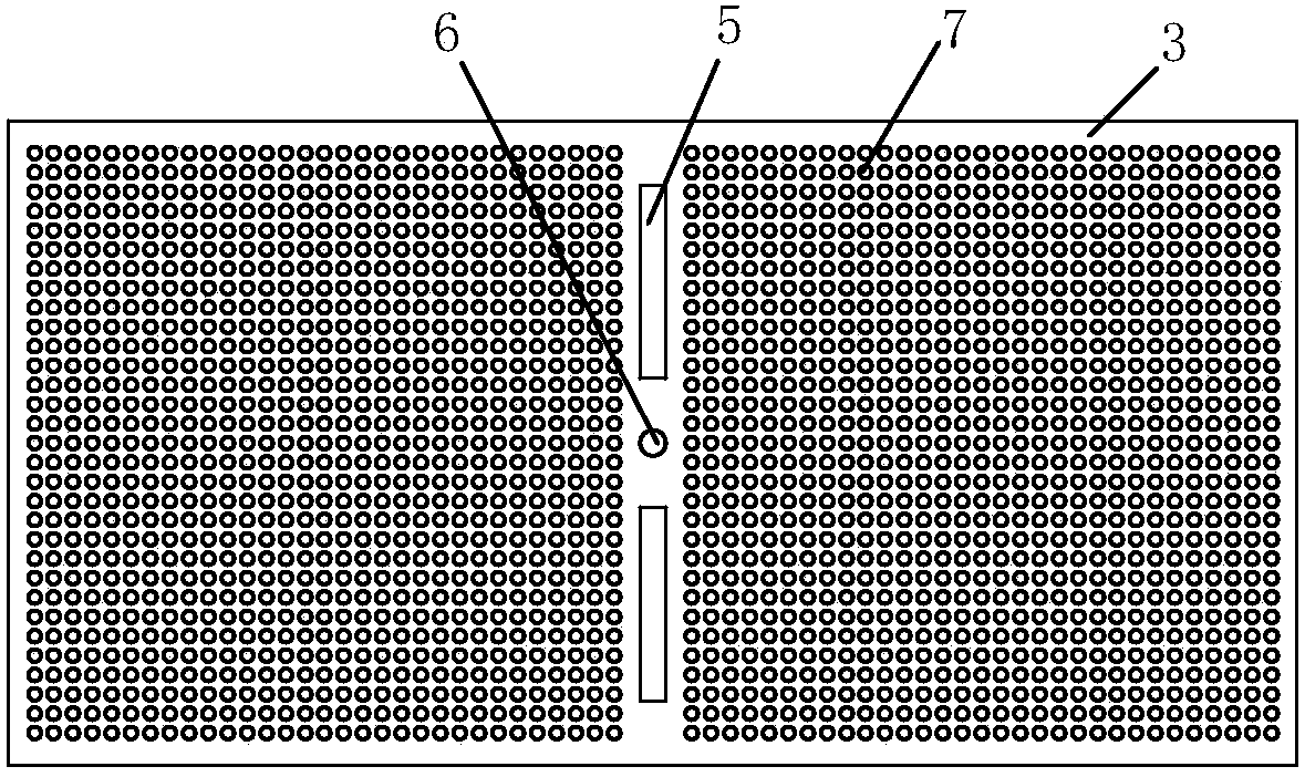
[0037] The calibration device of the infrared camera vision system includes an infrared backlight board 1, an infrared diffusion board 2, a metal chart card 3 and a processing terminal 4, wherein:

[0038] The infrared backlight panel 1 is used to provide a stable lighting environment for the metal chart card 3;

[0039] The infrared di...


PUM


Abstract

The invention relates to the technical field of camera calibration and provides a calibration device for an infrared camera visual system and a calibration method. The device comprises an infrared backlight board, an infrared diffusion board, a metal graph card and a processing terminal, wherein the infrared backlight board is used for providing a stable illumination environment for the metal graph card, the infrared diffusion board is used for uniformly diffusing illumination provided by the infrared backlight board onto the metal graph card, the metal graph card is used for providing a stable test pattern for a to-be-calibrated infrared camera, the processing terminal is used for carrying out calibration and calculation of a test image acquired by the to-be-calibrated infrared camera to acquire a proportional relationship between the test image and the metal graph card, the proportional relationship between the test image and the metal graph card comprises a proportional function of a test image distance and a practical scene distance, and thereby monitoring on distortion of the infrared camera and coordinate calibration of the visual system are realized. The device is advantaged in that operation is simple, cost is relatively low, and detection efficiency is high.

Description

technical field [0001] The invention belongs to the technical field of camera calibration, and in particular relates to a calibration device and a calibration method for an infrared camera vision system. Background technique [0002] Infrared cameras are widely used in electronic products such as military industry and virtual games. In these applications, in order to eliminate the influence of camera distortion, it is necessary to calibrate the vision system of the infrared camera. The purpose is to match the coordinate system of the image captured by the infrared camera with the coordinate system of the actual scene. correspond. Due to the particularity of the infrared camera, it does not receive visible light, so it is impossible to calibrate the camera with ordinary film charts or optical glass charts, and no calibration device for the infrared camera vision system has been found yet. Contents of the invention [0003] The purpose of the present invention is to provide...

Claims


Application Information

Patent Timeline
Patent Type & Authority Patents(China)
IPC IPC(8): G06T7/80
CPCG06T2207/10048G06T2207/30204
Inventor 翟霈徐博刘占发刘铁伟
Owner GEER TECH CO LTD
Learn More