Wafer divider and wafer division method

一种晶片、载置的技术,应用在精细的工作装置、电气元件、电固体器件等方向,能够解决增加分割、分割晶片、困难等问题

Active Publication Date: 2016-08-31
DISCO CORP
View PDF11 Cites 1 Cited by
  • Summary
  • Abstract
  • Description
  • Claims
  • Application Information

AI Technical Summary

Problems solved by technology

[0004] However, when the wafer is divided into chips whose outer shape is not quadrangular but hexagonal, octagonal or 12-sided, since the planned dividing line according to the outer shape of the chip is not a unidirectional straight line, it cannot Divide the wafer against the cutting tool
In addition, in the case of dividing the wafer into 12-sided chips, unnecessary triangular offcuts surrounded by 3 12-sided chips are formed, which increases the factor that makes the division difficult.

Method used


Image

  • Wafer divider and wafer division method
  • Wafer divider and wafer division method
  • Wafer divider and wafer division method

Examples


Embodiment Construction

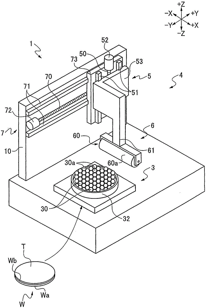
[0025] figure 1 The shown splitting device 1 is a device for splitting a wafer W placed on a mounting table 3 into a plurality of chips by a splitting unit 4 .

[0026] Such as figure 1 As shown, a mounting table 3 is disposed on the dividing device 1 . The mounting table 3 has a plurality of spherical bodies 30 and a container 32 for accommodating the plurality of spherical bodies 30 in close contact.

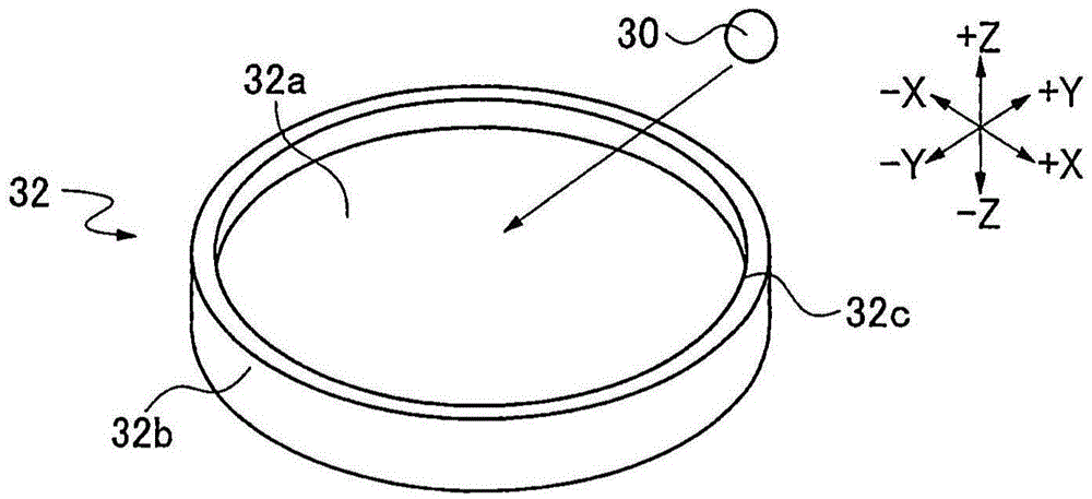
[0027] figure 2 The shown container 32 is composed of, for example, a disc-shaped bottom plate 32a and a side plate 32b vertically erected from the outer peripheral portion of the bottom plate 32a in the +Z direction, and can be placed in the same space in the space surrounded by the bottom plate 32a and the side plate 32b. The spherical body 30 is arranged in a plurality of spaces of the diameter. In addition, the outer shape of the bottom plate 32a is not limited to a disc shape, and may be a quadrangle or the like.

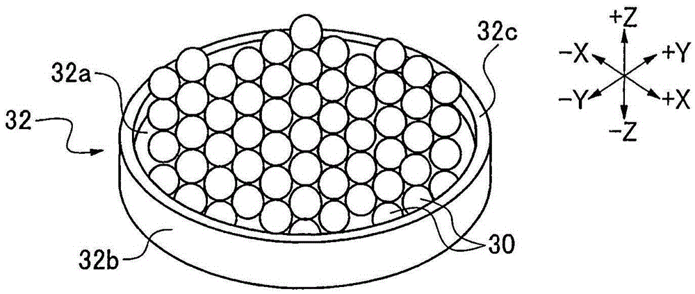
[0028] Such as image 3 As shown, in the space sur...


PUM


Abstract

A divider which divides a wafer having a division start points formed along the scheduled divisions into a plurality of device chips. The divider includes a placement table on which a wafer is placed, and division unit adapted to divide the wafer on the placement table into a plurality of device chips starting from the division start points. The placement table includes: a plurality of spherical bodies having the same diameter; a container that accommodates the plurality of spherical bodies in close contact with each other; and a placement surface formed by connecting vertices of spherical surfaces of the plurality of spherical bodies that are accommodated in close contact with each other.

Description

technical field [0001] The present invention relates to a dividing device for dividing a wafer and a method for dividing the wafer. Background technique [0002] In a wafer, a plurality of devices such as ICs and LSIs are divided by dividing lines and formed on the front surface. As a method of dividing the wafer into chips for each device, there is a method of forming a dividing start point along the dividing line, The cutting blade pushes against the dividing starting point to break the planned dividing line (for example, refer to Patent Document 1). [0003] Patent Document 1: Japanese Patent Laid-Open No. 2010-135484 [0004] However, when the wafer is divided into chips whose outer shape is not quadrangular but hexagonal, octagonal or 12-sided, since the planned dividing line according to the outer shape of the chip is not a unidirectional straight line, it cannot A cutting tool is used to separate the wafer. In addition, when the wafer is divided into chips having a...

Claims


Application Information

Patent Timeline
Patent Type & Authority Applications(China)
IPC IPC(8): H01L21/304H01L21/78H01L21/67
CPCH01L21/304H01L21/67092H01L21/78H01L2221/67H01L21/6875H01L21/68785B28D5/0011B28D5/0029B28D5/0052
Inventor 桐原直俊
Owner DISCO CORP
Why Eureka
Try Eureka