Switching room monitoring alarm system

A technology for monitoring alarms and power distribution rooms, which is used in control/regulation systems, non-electric variable control, substation/distribution device enclosures, etc. Easy to reduce, good cooling effect, low cost effect

Active Publication Date: 2016-08-31
NINGBO HI TECH S VIEW TECH
View PDF10 Cites 9 Cited by
  • Summary
  • Abstract
  • Description
  • Claims
  • Application Information

AI Technical Summary

Problems solved by technology

The closest existing technology of this patent application is: the patent No. 201320095798.3 "a distribution box with circulating cooling water", and the patent No. 201320599913.0 a ground temperature constant temperature circulator; but the above two patent solutions Relatively simple, poor cooling effect
On the other hand, the distribution room located in the field has no effective measures against fire
Because there are above-mentioned technical problems in prior art, affect use, therefore must improve

Method used


Image

  • Switching room monitoring alarm system
  • Switching room monitoring alarm system
  • Switching room monitoring alarm system

Examples


Embodiment 1

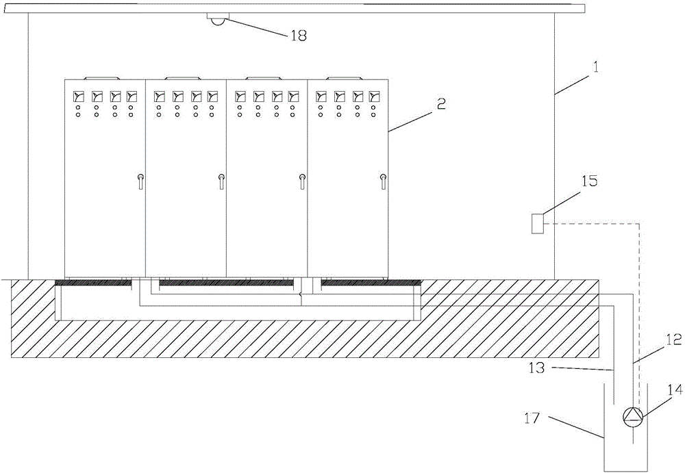
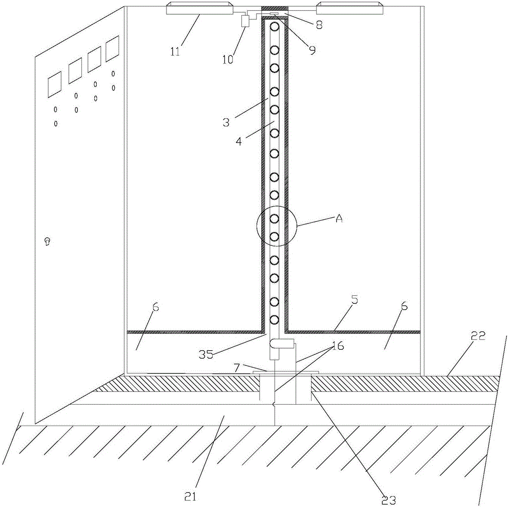
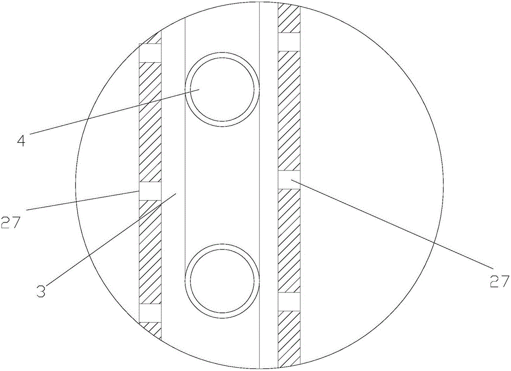
[0037] Such as figure 1 , 2 , 3, the monitoring and alarm system of the power distribution room described in this embodiment is provided with a plurality of power distribution cabinets 2 arranged side by side in the power distribution room 1, and the number of the power distribution cabinets 2 is an even number; Two adjacent power distribution cabinets 2 form a power distribution cabinet group, and a coil room 3 is arranged between the two power distribution cabinets 2 of each group, and a cooling coil 4 is arranged in the coil room 3; The two side walls of the coil room 3 are covered with overflow ports 27, and the overflow ports 27 are in the shape of through holes; the lower part of the power distribution cabinet 2 is separated from the air inlet chamber 6 by a transverse partition 5, and the two air inlet chambers of each group The chambers 6 communicate with each other, and the air inlet 35 at the bottom of the coil chamber 3 is located in the air inlet chamber 6. The fr...

Embodiment 2

[0041] Such as Figure 4 As shown, the monitoring and alarm system of the power distribution room described in this embodiment is substantially the same as that of Embodiment 1, except that: the ceiling of the power distribution room 1 is also provided with a monitoring camera 19; the monitoring camera 19 The signal is sent to the remote monitoring host 20 located in the central monitoring room;

[0042] The staff in the central monitoring room can observe the situation in the power distribution room 1, and send people to deal with it in case of any situation; the monitoring technology is existing and will not be described in detail.

Embodiment 3

[0044] Such as Figure 5 As shown, the monitoring and alarm system of the power distribution room described in this embodiment is substantially the same as that of Embodiment 1, except that: the cooling coil 4 has a plurality of parallel horizontal sections 26; A coil fixing block 24 is provided between the horizontal section 26 of the pipe 4 and the side wall of the coil chamber 3; each area corresponding to the horizontal section 26 of the cooling coil 4 on the side walls of the left and right coil chambers 3 is provided with Trapezoidal portion 25 protruding to the side; the cooling coil 4 is located in the trapezoidal portion 25, and the overflow port 27 is provided on the inclined upper top surface 28 of the trapezoidal portion 25, and the overflow port 27 is a long groove shape;

[0045] With such a structure, when the fan 11 is working and the cold air in the coil chamber 3 is drawn out through the overflow port 27, the replenished air source has sufficient contact wit...


PUM


Abstract

The invention discloses a switching room monitoring alarm system. A plurality of power distribution cabinets are parallelly arranged in a switching room; each two power distribution cabinets form a power distribution cabinet set; a coil chamber is arranged between two power distribution cabinets in each power distribution cabinet set, and is internally provided with a cooling coil; a communication area is arranged between two power distribution cabinets in each power distribution cabinet set, and is internally provided with a temperature probe; a temperature controller is arranged in one power distribution cabinet, and controls two fans in the set to work simultaneously; the lower portion of the power distribution cabinet is provided with a total cooling water supply pipe and a cooling water return pipe which are both in connection with a cooling water supply terminal; the ceiling of the switching room is provided with a fire alarm. The system can effectively monitor temperatures in power distribution cabinets to keep the temperatures within a safe and reasonable range, control a rate of temperature increase in power distribution cabinets to prevent fire, and ensure the normal operation of power distribution cabinet inner elements and the safety of an electric power system.

Description

technical field [0001] The invention relates to a monitoring system, in particular to a monitoring and alarm system for a power distribution room. Background technique [0002] The power distribution room is an important part of the power system. There is a power distribution cabinet in the power distribution room. The power distribution cabinet is used to place various electrical components required for power distribution. Electrical components are prone to heat during use. Once the temperature is too high It is easy to affect the work of electrical components, thereby bringing losses to the power system, so it is very important to monitor the temperature of the power distribution cabinet. The closest existing technology of this patent application is: the patent No. 201320095798.3 "a distribution box with circulating cooling water", and the patent No. 201320599913.0 a ground temperature constant temperature circulator; but the above two patent solutions Relatively simple, ...

Claims


Application Information

Patent Timeline
Patent Type & Authority Applications(China)
IPC IPC(8): H02B1/56G05D23/19A62C37/40
CPCA62C31/00A62C37/40G05D23/1931H02B1/28H02B1/32H02B1/56H02B1/565H02J13/00001
Inventor 过森君
Owner NINGBO HI TECH S VIEW TECH
Why Eureka
Try Eureka