Supercharge Your Innovation With Domain-Expert AI Agents!

Signaling and Frequency Offset Determination Using Multiple Correlators

A frequency offset and correlator technology, applied in the direction of synchronous signal speed/phase control, transmission path sub-channel allocation, transmission monitoring, etc., can solve the problem of data misreading, no carrier frequency offset or drift, etc.

Active Publication Date: 2019-09-17
NORDIC SEMICONDUCTOR
View PDF5 Cites 0 Cited by
  • Summary
  • Abstract
  • Description
  • Claims
  • Application Information

AI Technical Summary

Problems solved by technology

However, while this may help increase range under ideal conditions, it may not work with carrier frequency offset or drift
These can cause problems with data being misinterpreted when the signal is received

Method used


Image

  • Signaling and Frequency Offset Determination Using Multiple Correlators
  • Signaling and Frequency Offset Determination Using Multiple Correlators
  • Signaling and Frequency Offset Determination Using Multiple Correlators

Examples


Embodiment Construction

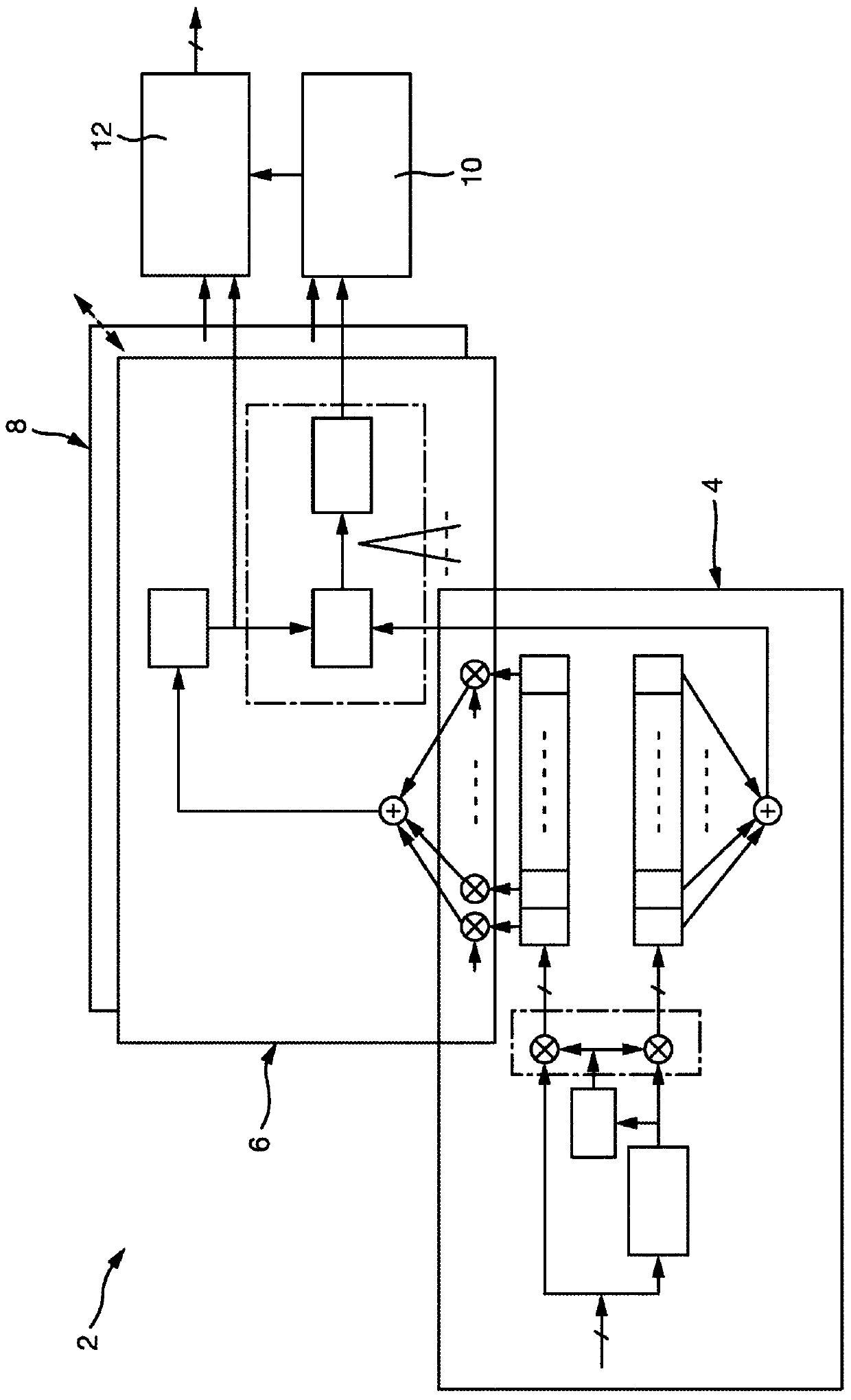
[0030] figure 1 A typical processor 2 of a digital receiver according to the invention is shown. The processor 2 is mainly composed of an estimator 4 and a pair of correlators 6,8. The correlators 6, 8 have the same physical setup, but are each associated with a different chip sequence. refer to figure 2 It is explained in more detail.

[0031] In this example there are two correlators, but in practice there may be more than two correlators depending on the number of sequences that need to be represented. The combination of correlators 6, 8 and estimator 4 forms a data assisted joint timing and frequency offset estimator.

[0032] In use, the common estimator 4 is used to synchronize the correlators 6,8. The correlators 6, 8 are also synchronized to the input signal by means of a finite state machine (FSM) 10 which schedules the sampling of the input signal so that the samples are considered appropriate to the received bit pattern. Since the input signal has been spread...


PUM


Abstract

A digital radio receiver 54 is adapted to receive radio signals which are modulated using continuous phase modulation. The receiver comprises means for receiving an analog radio signal having a carrier frequency; a plurality of correlators 6, 8, each corresponding to a different bit sequence, sharing a common estimator 4 for estimating the The frequency offset between said carrier frequency and the nominal carrier frequency, and means 12 for determining which of said correlators 6, 8 produces the desired output signal.

Description

technical field [0001] The present invention relates to apparatus and methods for decoding digital radio transmissions. Background technique [0002] In portable devices, there is a fundamental requirement to reduce power consumption. This requirement extends to the power used for the communication method, which can limit the range over which communication can efficiently take place. [0003] Although many different communication protocols exist, eg Bluetooth, Zigbee, their implementations have common limitations. In particular, signals become susceptible to noise, especially in long-distance transmissions where the signal attenuates with distance. This results in bit and packet errors when the data cannot be received accurately. One way to make the signal less affected by noise is of course to increase the power transmitted, since this increases the signal-to-noise ratio. However, this is inconsistent with efforts to reduce power consumption, and the two requirements mu...

Claims


Application Information

Patent Timeline
Patent Type & Authority Patents(China)
IPC IPC(8): H04B1/708H04B1/7087H04L7/04H04W4/80
CPCH04L27/0014H04L27/227H04L2027/0026H04L2027/0034H04L2027/0046H04W4/80H04B1/7087H04B1/708H04L27/2657H04L27/2663H04B17/336H04B2201/69H04L5/006
Inventor 大卫·亚历山大·恩格林恩-洛佩斯斯韦勒·维驰隆德菲尔·科比什利
Owner NORDIC SEMICONDUCTOR
Features
  • R&D
  • Intellectual Property
  • Life Sciences
  • Materials
  • Tech Scout
  • Unparalleled Data Quality
  • Higher Quality Content
  • 60% Fewer Hallucinations
Learn More