End punching die of automotive chassis suspension upper bending pipe fitting semi-finished product

A technology for automobile chassis and bending pipes, which is used in perforating tools, manufacturing tools, metal processing equipment, etc., can solve the problems of inability to connect production, high logistics turnover costs, and low production efficiency of CNC machine tools.

Inactive Publication Date: 2016-09-07
苏州金鸿顺汽车部件股份有限公司
View PDF12 Cites 1 Cited by
  • Summary
  • Abstract
  • Description
  • Claims
  • Application Information

AI Technical Summary

Problems solved by technology

The reason for not using stamping dies for stamping production is that due to the bending and flattening of the ends, the general punching structure is difficult to solve the problem of stamping deformation of the workpiece, and the punching stability is poor; and the discharge of punching waste is also a problem
[0003] However, the drilling efficiency of CNC machine tools is low, because the drilling time of CNC machine tools is 5-6 times that of stamping.
Moreover, the logistics turnover cost is high, because the pre-process of pipe fittings needs to be transferred to the machining workshop after being formed by cold stamping, which requires material turnover and cannot be connected to production

Method used


Image

  • End punching die of automotive chassis suspension upper bending pipe fitting semi-finished product
  • End punching die of automotive chassis suspension upper bending pipe fitting semi-finished product
  • End punching die of automotive chassis suspension upper bending pipe fitting semi-finished product

Examples


Embodiment Construction

[0026] Specific embodiments of the present invention will be described in detail below in conjunction with the accompanying drawings.

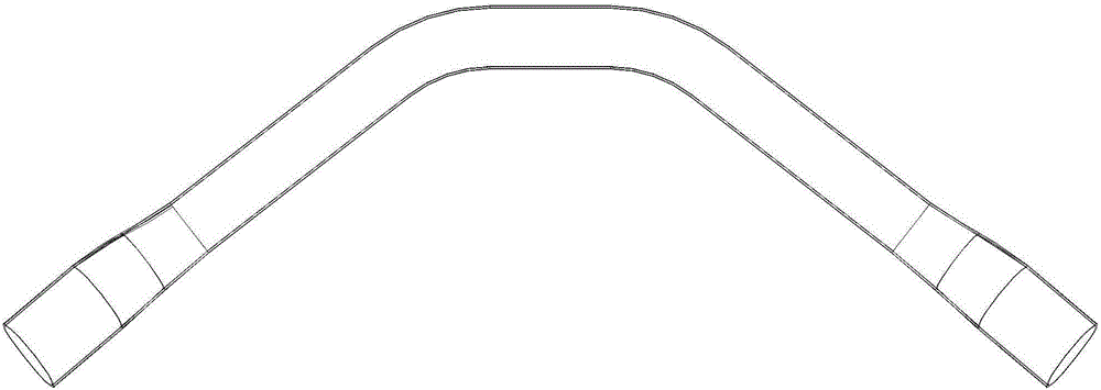
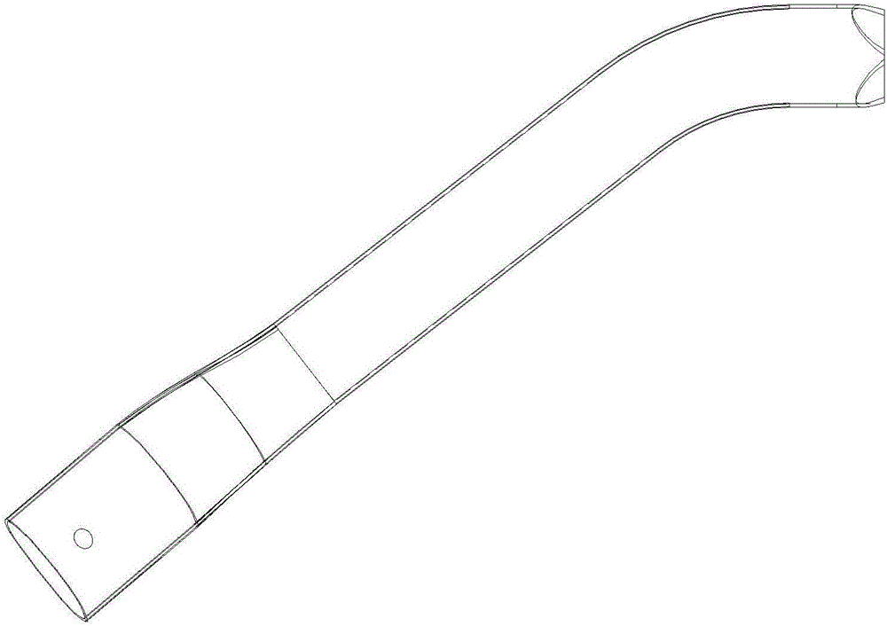
[0027] like Figure 4 As shown in -5, an end punching die for the semi-finished product of bending pipe fittings on the chassis suspension of an automobile, including an upper mold base 8 and a lower mold base 1;

[0028] The lower mold base 1 is provided with a left material holder 2 and a right material holder 3 arranged side by side. The left material chute, the right material chute 3 is provided with the right material chute, and the lower mold base 1 is provided with sliding blocks 4 at the two ends of the left material 2 and the right 3 respectively, The lower mold base 1 is provided with four nitrogen gas springs that respectively drive the four sliding blocks 4 to reset. The sliding block 4 is provided with a mandrel 5 that matches the shape of the inner end surface of the workpiece to be processed. The corresponding forming hole of ...


PUM


Abstract

The invention discloses an end punching die of an automotive chassis suspension upper bending pipe fitting semi-finished product. The end punching die is high in production efficiency and machining accuracy and comprises an upper die base and a lower die base, wherein a left accommodating base and a right accommodating base are arranged on the lower die base side by side; sliding blocks are arranged at two ends of the left accommodating base and the right accommodating base on the lower die base; core rods are arranged on the sliding blocks and are matched with the inner end face of a to-be-machined workpiece in shape; forming holes corresponding to workpiece to-be-machined holes are formed in the core rods; a driving oblique plane is arranged on a sliding base; a left pressing block and a right pressing block are arranged on the upper die base; four driving tapered wedges capable of driving corresponding sliding block to slide are arranged on the upper die base; forming blocks are arranged at two ends of the left pressing block and the right pressing block on the upper die base; upper accommodating grooves are formed in the upper forming blocks; punches are arranged in the upper accommodating grooves in the upper forming blocks, and the axis of each punch is parallel to that of the to-be-machined hole; pressed oblique planes are arranged on the upper forming blocks; stamping tapered wedges capable of driving the upper forming block to slide are arranged on the lower die base.

Description

technical field [0001] The invention relates to an end punching die for a semi-finished product of a bent pipe fitting on an automobile chassis suspension. Background technique [0002] A semi-finished product of bending pipe fittings on the chassis suspension of an automobile such as Figure 1-2 As shown, the semi-finished product needs to be processed through multiple processes such as end punching. After processing, it can be cut from the middle to obtain two symmetrical finished products, such as image 3 shown. Both ends of the semi-finished product need to have through holes, and the holes are required not to be deformed. In the industry, CNC machine tools are usually used for drilling, and special fixtures are used for clamping and fixing to ensure the tolerance size of the holes. The reason why stamping dies are not used for stamping production is that due to the bending and flattening of the ends, the general punching structure is difficult to solve the stamping de...

Claims


Application Information

Patent Timeline
Patent Type & Authority Applications(China)
IPC IPC(8): B21D28/34B21D28/28
CPCB21D28/34B21D28/28
Inventor 徐锋来
Owner 苏州金鸿顺汽车部件股份有限公司
Why Eureka
Try Eureka