Automatic stamping equipment for thin-walled annular workpieces

A technology of annular workpiece and stamping equipment, applied in the field of stamping die, can solve the problems of only sampling inspection, low efficiency, difficult displacement positioning, etc., and achieve the effect of improving production efficiency and yield, reducing labor intensity and improving production efficiency.

Active Publication Date: 2016-09-07
河北昊天滤清器制造有限公司
View PDF9 Cites 4 Cited by
  • Summary
  • Abstract
  • Description
  • Claims
  • Application Information

AI Technical Summary

Problems solved by technology

[0004] However, there are great difficulties in using progressive stamping dies for two ring-shaped workpieces with different cross-sectional areas. One is that the thin-walled workpieces are stamped from thin-walled steel strips. The deformation itself is large, and the strength of the steel strip is small, and the displacement positioning is difficult, which leads to inaccurate positions of multiple stations and low product yield. The process is complicated; the third is that after stamping and forming, its size needs to be tested, especially the axial height. During the stamping process, the axial height will be unqualified, and the radial thickness will not deform much during the stamping process. Inspection, in the production process of annular workpieces with different cross-sectional areas, molds are needed in the stamping process, and corresponding molds are also required in the testing process. After stamping is completed, the product is taken out of the stamping mold and then installed in the testing mold for testing , not only time-consuming and laborious, but also inefficient, only random inspections can be carried out, and every finished product cannot be inspected. Therefore, product quality cannot be fully guaranteed

Method used


Image

  • Automatic stamping equipment for thin-walled annular workpieces
  • Automatic stamping equipment for thin-walled annular workpieces
  • Automatic stamping equipment for thin-walled annular workpieces

Examples


Embodiment Construction

[0028] Below in conjunction with the accompanying drawings, the present invention will be described in detail through specific embodiments, but the use and purpose of these exemplary embodiments are only used to illustrate the present invention, and do not constitute any form of any limitation on the actual protection scope of the present invention, let alone The protection scope of the present invention is limited thereto.

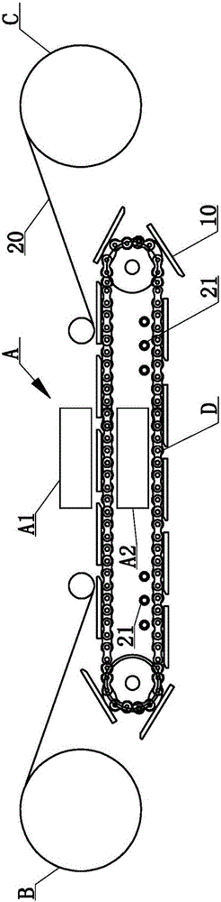
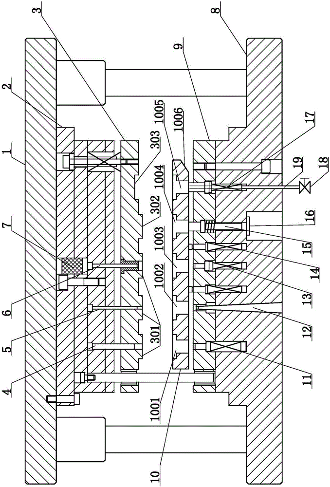
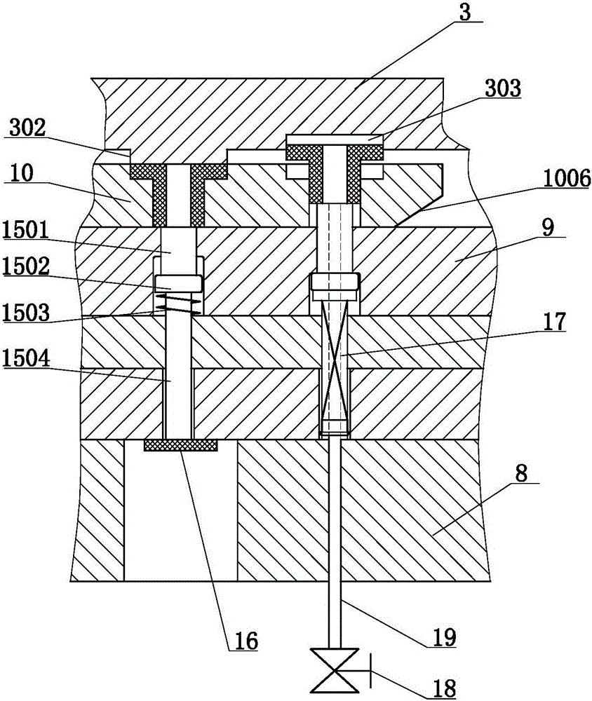
[0029] Such as figure 1 , figure 2 , image 3 and Figure 4Commonly shown, the present invention discloses an automatic stamping device for a thin-walled annular workpiece, which includes a stamping die A, the stamping die A includes an upper die part A1 and a lower die part A2, and the upper die part A1 includes an upper die base 1 and a connecting plate 2 and the stamping plate 3, the connecting plate 2 is fixedly connected with the upper die base 1, the connecting plate 2 is elastically connected with the stamping plate 3, the lower die part A2 inc...


PUM


Abstract

The invention discloses automatic stamping equipment for thin-walled annular workpieces and belongs to the technical field of stamping dies. The automatic stamping equipment comprises a stamping die, wherein the stamping die comprises an upper die part and a lower die part, the upper die part comprises an upper die holder, a connecting plate and a stamping plate, and the lower die part comprises a lower die holder and a lower die plate which are fixed and mounted together; a drawing male die, a punching male die and a shaping male die are sequentially mounted on the connecting plate of the upper die part, stamping convex rings surrounding all of the drawing male die, the punching male die and the shaping male die are arranged on the stamping plate, and a drawing elastic ejector, a blanking hole and a shaping elastic ejector are sequentially and correspondingly arranged on the lower die plate of the lower die part; and a molding die plate mounted on a circulating chain is arranged between the stamping plate and the lower die plate, and a drawing female die, a blanking female die and a shaping female die are sequentially arranged on the molding die plate. The automatic stamping equipment can realize the processing of the annular workpieces with different cross areas on the progressive stamping die, improves the production efficiency and the finished product rate and is widely applied to the manufacture of the annular workpieces with different cross areas.

Description

technical field [0001] The invention relates to the technical field of stamping dies, in particular to automatic stamping equipment for thin-walled annular workpieces. Background technique [0002] There is a thin-walled annular product in production, which is shaped like a ring with a large cross-sectional area and a ring with a small cross-sectional area connected together, and there is a central hole in the middle, and the wall thickness of the ring with a small cross-sectional area is only 0.8 mm. , belongs to thin-walled products, which are difficult to process. At present, in order to apply to mass production, most of them are processed by stamping dies. [0003] Among the stamping dies, the progressive stamping die has attracted much attention due to its continuous production and high production efficiency. The progressive stamping die refers to the process in which the press completes multiple stamping processes at several different positions of the die at the same t...

Claims


Application Information

Patent Timeline
Patent Type & Authority Applications(China)
IPC IPC(8): B21D37/08B21D35/00B21D45/02B21C51/00B21D43/00
CPCB21C51/00B21D35/001B21D37/08B21D43/003B21D45/02
Inventor 刘晓丽
Owner 河北昊天滤清器制造有限公司
Why Eureka
Try Eureka