Packaging bag opening device

A packaging bag and piston rod technology, applied in the field of packaging bag opening device, can solve the problems of high energy consumption, large space occupation of vacuum pump, complicated maintenance of solenoid valve and electric control, etc., and achieve the effect of stable operation

Inactive Publication Date: 2016-09-07
李正元
View PDF8 Cites 9 Cited by
  • Summary
  • Abstract
  • Description
  • Claims
  • Application Information

AI Technical Summary

Problems solved by technology

[0004] In actual production, the use of vacuum pumps requires air pipes to be connected to solenoid valves and controlled by circuits. In some small mechanical structures, it takes up a lot of

Method used


Image

  • Packaging bag opening device
  • Packaging bag opening device
  • Packaging bag opening device

Examples


Embodiment 1

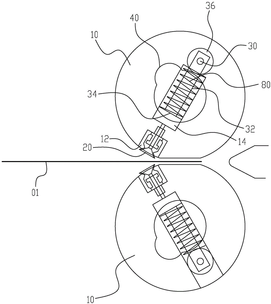
[0028] Please refer to figure 1 , a packaging bag opening device of the present invention includes two rollers 10 symmetrically arranged on both sides of the packaging bag 01, the outer peripheral surface of the rollers 10 is provided with a suction nozzle 20, and the outer surface of the rollers 10 is A groove 12 is provided, and the suction nozzle 20 is located in the groove 12; the suction nozzle 20 is connected with a suction mechanism 30 for pumping air and generating suction, the suction nozzle 20, the roller 10, the suction mechanism 30 and the three rotate synchronously; the pumping mechanism 30 includes a reciprocatingly movable piston rod 32, a piston 34 connected to the bottom end of the piston rod 32, and a bearing 36 connected to the top end of the piston rod 32; When leaning on the packaging bag 01, push the piston rod 32 to move upwards to make the suction nozzle 20 generate suction to absorb the fixed bump 40 of the packaging bag 01, and to push the piston rod ...

Embodiment 2

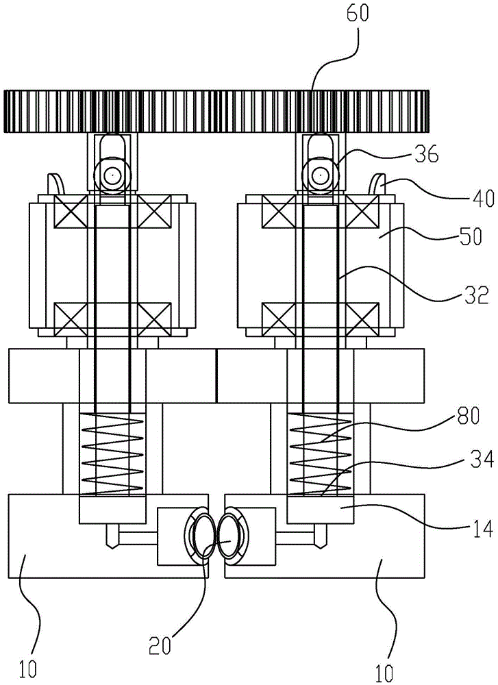
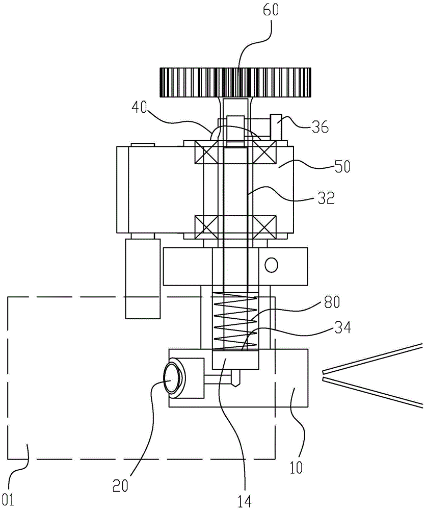
[0032] Please refer to Figure 2 to Figure 4 The difference between the second embodiment and the first embodiment is that the chamber 14 has a circular groove structure and is located at the center of the end surface of the roller 10; it also includes a bearing seat 50 through which the piston rod 32 passes; the bearing 36 is connected On the side of the piston rod 32 top, the fixed projection 40 is arranged above the bearing seat 50, and the fixed projection 40 and the bearing seat 50 are located on the same circumference; the top of the piston rod 32 is connected with a gear 60, and the two piston rods 32 The gear 60 is engaged; the reset member 80 is sleeved on the piston rod 32 and generates a downward force on the piston 34 .

[0033] By arranging the bearing seat 50 and extending the piston rod 32 to the outside of the roller 10, the moment arm can be increased, so that the suction mechanism can generate greater suction force.

[0034] The piston rod 32 and the bearing...


PUM


Abstract

The invention discloses a packaging bag opening device, which comprises two rollers symmetrically arranged on front and back sides of a packaging bag. The outer peripheral surface of each roller is provided with a suction nozzle which is connected with an air exhaust mechanism for air exhaust and suction generation. The suction nozzles, the rollers and the air exhaust mechanisms rotate synchronously. Each air exhaust mechanism includes a reciprocable piston rod and a piston connected at the bottom end of the piston rod; and further comprises a fixing projection for pushing the corresponding piston rod to move upward when the corresponding suction nozzle abuts against the packaging bag so that the suction nozzle can generate the suction to suck the packaging bag, and a reset member for pushing the corresponding piston rod to move downward to enable the corresponding suction nozzle to release the suction. The fixing projections push the piston rods to move upward so that the suction nozzles can generate suction to suck the packaging bag, and thus an opening of the packaging bag is enabled to automatically open when the packaging bag is outputted. According to the invention, the locations of the fixing projections remain unchanged, the piston rods only make contact with the fixing projections each time when moving in a circular motion to the fixing points, and the packaging bag opening device runs quite stably.

Description

technical field [0001] The invention relates to a packaging bag opening device. Background technique [0002] Packaging bags are very commonly used daily necessities in daily life, and are also frequently used in industrial production processes. When the packaging bag is in use, its opening needs to be opened manually so that the articles can be packed into the packaging bag. [0003] In order to improve production efficiency, in industrial production workshops, most people use machinery and equipment to automatically open the packaging bag. The principle is to use a vacuum pump to generate negative pressure and connect a pair of suction cups with a pipeline to respectively suck the front and back of the packaging bag, and then drive it through the cylinder. The two suction cups move back to open the opening of the packaging bag. [0004] In actual production, the use of vacuum pumps requires air pipes to be connected to solenoid valves and controlled by circuits. In some ...

Claims


Application Information

Patent Timeline
IPC IPC(8): B65B43/30
CPCB65B43/30
Inventor 李正元
Owner 李正元
Why Eureka
Try Eureka