Method of detecting the quality of grouting after pile foundation by using distributed optical fiber temperature measurement technology

A distributed optical fiber and technical detection technology, which is applied in infrastructure testing, infrastructure engineering, construction, etc., can solve problems such as the difficulty of judging the quality of grouting construction, achieve simple and firm devices, and improve detection efficiency Effect

Active Publication Date: 2018-11-13
ZHEJIANG UNIV OF TECH
View PDF4 Cites 0 Cited by
  • Summary
  • Abstract
  • Description
  • Claims
  • Application Information

AI Technical Summary

Problems solved by technology

[0005] In order to solve the defect that it is difficult to judge the quality of grouting construction after grouting in existing pile foundations, the present invention provides a method of real-time detection and precise positioning of temperature changes around piles before and after grouting through distributed optical fiber temperature measurement technology. A new method to detect the grouting quality of the pile foundation by using the distributed optical fiber temperature measurement technology to detect the grouting effect

Method used


Image

  • Method of detecting the quality of grouting after pile foundation by using distributed optical fiber temperature measurement technology
  • Method of detecting the quality of grouting after pile foundation by using distributed optical fiber temperature measurement technology
  • Method of detecting the quality of grouting after pile foundation by using distributed optical fiber temperature measurement technology

Examples


Embodiment Construction

[0031] refer to Figure 1a to Figure 7 , a new method of detecting the quality of post-pile grouting using distributed optical fiber temperature measurement technology, including the following steps:

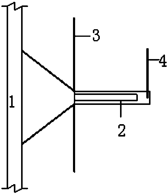
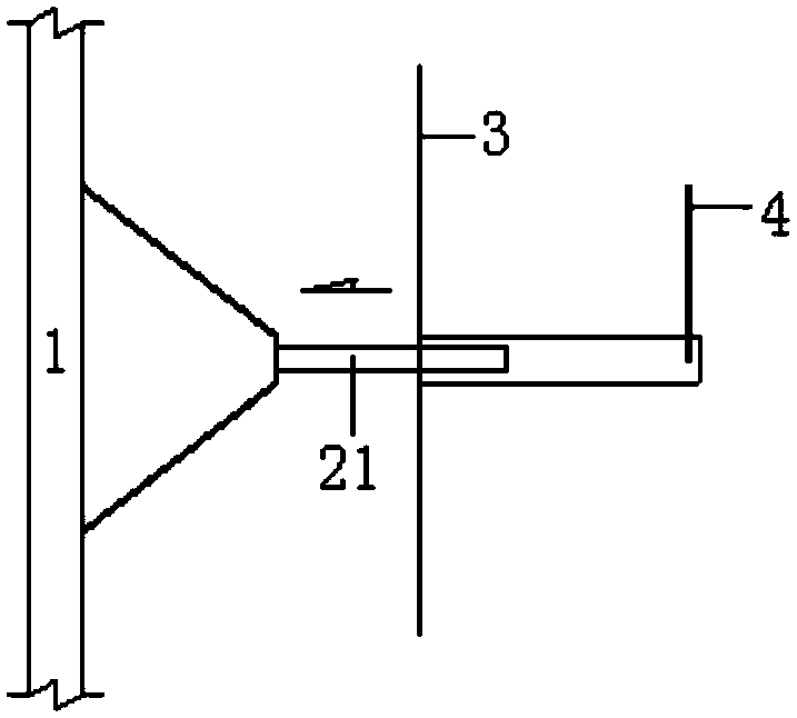
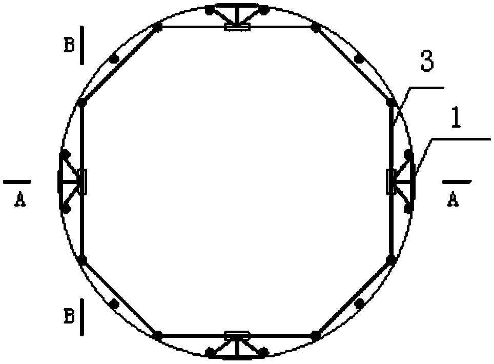
[0032] (1), install the sensing temperature measuring optical fiber: fix the sensing temperature measuring optical fiber 1 with the hydraulic cylinder or the pneumatic cylinder 2 on the main rib 51 of the steel cage 5, the sensing temperature measuring optical fiber 1 is connected with the hydraulic cylinder or the air pressure The piston rod 21 of the cylinder 2 is fixedly connected, and the acquisition signal input end of the external collector 7 is connected to the output end of the sensing temperature-measuring optical fiber 1; the sensing temperature-measuring optical fiber 1 is arranged in a U-shaped structure, and the The bottom of the bottom starts to be arranged upwards; the measurement cables, hydraulic pipes or air pressure pipes 4 are bound to the main reinforcement ...


PUM


Abstract

The invention relates to a new method for applying a distributed type fiber temperature measuring technology to detecting quality of pile foundation post grouting. The method comprises the steps that firstly, a sensing temperature measuring optical fiber is mounted, wherein the sensing temperature measuring optical fiber with a hydraulic cylinder or a pneumatic cylinder is fixed to a main rib of a steel reinforcement cage, and the sensing temperature measuring optical fiber is arranged to be of a U-shaped structure, and begins to be arranged upwards in a lengthening manner from the bottom of the steel reinforcement cage; secondly, the steel reinforcement cage is mounted; thirdly, the sensing temperature measuring optical fiber is ejected out, wherein the hydraulic cylinder or the pneumatic cylinder is used for ejecting out the sensing temperature measuring optical fiber, and the ejected-out sensing temperature measuring optical fiber is in contact with the hole wall of a cast-in-place pile; fourthly, concrete is poured into a pile hole of the cast-in-place pile; fifthly, after the strength of the concrete reaches 70% or more of designed strength, a collection instrument is used for reading the full-depth soil temperature value before grouting; sixthly, grouting is carried out; and seventhly, grouting is ended, after curing and reinforcing, the collection instrument is used for reading the full-depth soil temperature value after grouting, and through comparison of the temperature value before grouting and the temperature value after grouting, the distribution state of grout in pile side soil can be obtained.

Description

technical field [0001] The invention relates to a new method for detecting the quality of grouting after pile foundation by using distributed optical fiber temperature measurement technology, which belongs to the field of detection of bridge pile foundations, and specifically relates to the method of using distributed It is a method to evaluate the effect of grouting by optical fiber temperature measurement technology. Background technique [0002] The post-pile grouting technology can effectively reduce the pile length and improve the bearing capacity of cast-in-situ piles by injecting grout that can cement and solidify the pile tip and pile side soil to strengthen and solidify the pile tip and pile side soil. It has the advantages of reducing pile settlement, shortening the construction period, and reducing the engineering cost of cast-in-situ piles. The post-pile grouting technology has obvious advantages and good application prospects. In recent years, it has been widely...

Claims


Application Information

Patent Timeline
Patent Type & Authority Patents(China)
IPC IPC(8): E02D33/00
CPCE02D33/00E02D2250/003E02D2600/10
Inventor 卢彭真
Owner ZHEJIANG UNIV OF TECH
Why Eureka
Try Eureka