Compressing mechanism and rotary compressor

A compression mechanism and compression chamber technology, applied in the direction of rotary piston machines, rotary piston pumps, machines/engines, etc., can solve the problems of compressor capacity attenuation, refrigerant volume reduction, etc., and achieve high system energy efficiency and operational reliability Effect

Inactive Publication Date: 2016-09-07
ANHUI MEIZHI PRECISION MFG +1
View PDF11 Cites 4 Cited by
  • Summary
  • Abstract
  • Description
  • Claims
  • Application Information

AI Technical Summary

Problems solved by technology

[0002] In the related art, the liquid storage structure of the rotary compressor includes a motor and a compression mechanism part arranged in the casing. The motor is connected to the crankshaft in the compression mechanism part. The shaft drives the crankshaft that the piston rotates eccentrically and the upper bearing and the lower bearing that support the crankshaft. The upper bearing and the lower bearing are arranged on the cylinder, and the end surfaces of the piston and the end surfaces of the upper bearing and the lower bearing in the cylinder are respectively in gap contact and slide relative to each other. There is a liquid storage chamber in the cylinder, and the liquid storage chamber is composed of the cylinder, upper bearing, lower bearing and other components. However, due to the high temperature inside the liquid storage chamber, when the low-temperature and low-pressure refrigerant gas flows through the liquid storage chamber, there is suction overheating. , leading to a decrease in the unit amount of refrigerant entering the compression part of the pump body, and the capacity of the compressor is attenuated

Method used


Image

  • Compressing mechanism and rotary compressor
  • Compressing mechanism and rotary compressor
  • Compressing mechanism and rotary compressor

Examples


Embodiment 1

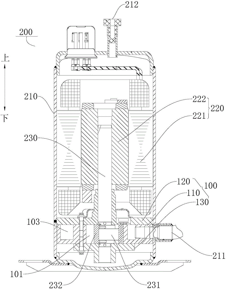
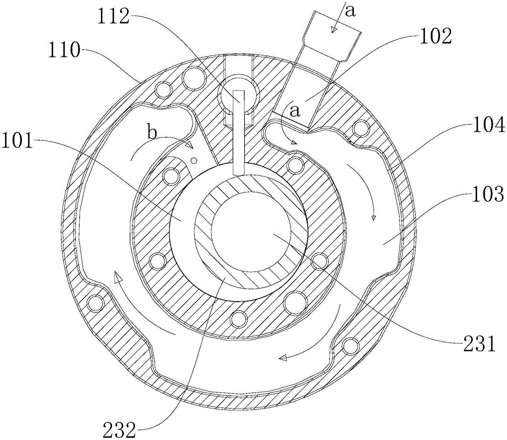
[0047] Such as Figure 1-Figure 5 As shown, in this embodiment, rotary compressor 200 includes housing 210 , motor assembly 220 , crankshaft 230 and compression mechanism 100 . Wherein, the casing 210 has a suction port 211 and an exhaust port 212 , and the motor assembly 220 and the compression mechanism 100 are both arranged in the casing 210 . The compression mechanism 100 may include a cylinder 110, an upper bearing 120 and a lower bearing 130. The cylinder 110 is sandwiched between the upper bearing 120 and the lower bearing 130. The cylinder 110 has a compression chamber 101 and a liquid storage space 111 with an open upper end. The liquid storage chamber 103 is jointly constructed by the liquid storage space 111 and part of the lower end surface of the upper bearing 120 . The compression chamber 101 communicates with the liquid storage chamber 103 , and the liquid storage chamber 103 communicates with the outside through the refrigerant channel 102 . Refrigerant can b...

Embodiment 2

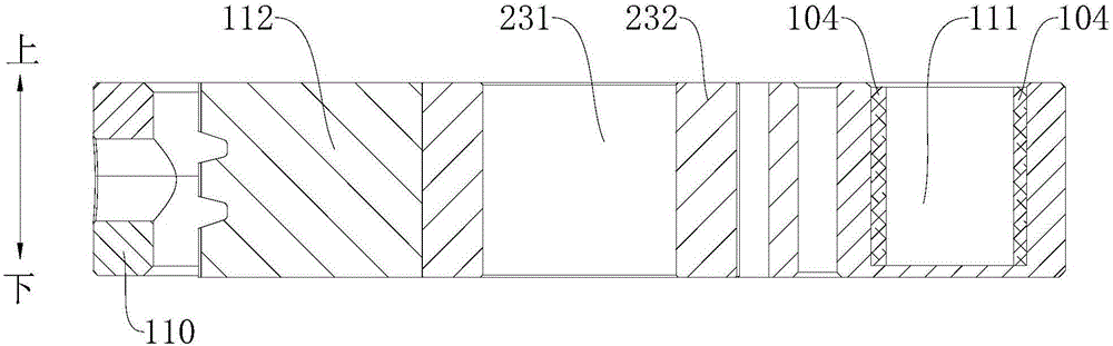
[0052] Such as Figure 6-Figure 7 As shown, the difference from Embodiment 1 is that in this embodiment, the heat insulating member 104 is formed as a profiling plastic part, and the profiling plastic part covers the entire inner wall of the liquid storage chamber 103, which can simulate the liquid storage chamber 103 After injection molding or blow molding, the profiling plastic part is built into the liquid storage chamber 103 so that it is in close contact with the inner wall of the liquid storage chamber 103. When the refrigerant gas flows in the profiling plastic part, due to the contact with the cylinder 110 If the cavities are not in contact, it will also have a good heat insulation effect, thereby improving the suction superheat and improving the energy efficiency and reliability of the rotary compressor 200 .

[0053] This profiled plastic is mainly composed of polyurethane (PU), polyethylene terephthalate (PET, PETE), polybutylene terephthalate (PBT), polyphenylene s...


PUM


Abstract

The invention discloses a compressing mechanism and a rotary compressor. A compressing cavity, a refrigerant channel and a liquid storage cavity are defined in the compressing mechanism; the compressing cavity communicates with the liquid storage cavity; the liquid storage cavity communicates with the outside by the aid of the refrigerant channel; and heat insulating pieces are laid on at least part of the inner wall of the liquid storage cavity. According to the compressing mechanism, the heat insulating pieces are laid on at least part of the inner wall of the liquid storage cavity, when a refrigerant gas flows in the liquid storage cavity, a refrigerant does not make direct contact with an air cylinder, and the suction overheating phenomenon of the compressing mechanism in the operation process can be effectively controlled, so that the compressing mechanism can have relatively high system energy efficiency and operation reliability.

Description

technical field [0001] The present invention relates to the technical field of refrigeration equipment, in particular to a compression mechanism and a rotary compressor. Background technique [0002] In the related art, the liquid storage structure of the rotary compressor includes a motor and a compression mechanism part arranged in the casing. The motor is connected to the crankshaft in the compression mechanism part. The shaft drives the crankshaft that the piston rotates eccentrically and the upper bearing and the lower bearing that support the crankshaft. The upper bearing and the lower bearing are arranged on the cylinder, and the end surfaces of the piston and the end surfaces of the upper bearing and the lower bearing in the cylinder are respectively in gap contact and slide relative to each other. There is a liquid storage chamber in the cylinder, and the liquid storage chamber is composed of the cylinder, upper bearing, lower bearing and other components. However, ...

Claims


Application Information

Patent Timeline
Patent Type & Authority Applications(China)
IPC IPC(8): F04C18/356F04C29/04F04C29/00
CPCF04C18/3564F04C29/00F04C29/04F04C2240/50F05C2203/0895F05C2225/00
Inventor 王小伟
Owner ANHUI MEIZHI PRECISION MFG
Why Eureka
Try Eureka