
Ankle-foot prosthesis device

a prosthesis device and klefoot technology, applied in the field of klefoot prosthesis devices, can solve the problems of inability to provide net positive work, hindering the rehabilitation of transtibial amputees with passive prosthesis, and hindering the rehabilitation of more natural gait behavior of transtibial amputees, so as to achieve the reduction of system energy consumption, torque and power requirements of actuators, and mechanical energy. negative

Active Publication Date: 2019-09-10
THE CHINESE UNIVERSITY OF HONG KONG
View PDF5 Cites 1 Cited by
  • Summary
  • Abstract
  • Description
  • Claims
  • Application Information

AI Technical Summary

Benefits of technology

The solution significantly decreases energy consumption, reduces actuator torque and power needs, and enables a nearly normal gait by using the elastic components to reproduce human ankle stiffness and propulsion, improving energy efficiency and extending battery life.

Problems solved by technology

As passive transtibial prostheses do not contain actuators, these cannot provide net positive work during a gait cycle, as does an intact human ankle.
This lack of positive work hinders amputees from restoring a more natural gait behavior.
However, clinical studies showed that due to the inability of passive prostheses to supply net positive work across the stance, transtibial amputees with passive prostheses have various problems during walking, such as non-symmetric gait patterns and higher metabolic cost as compared to the gait of intact individuals.
However, powered prostheses present certain challenges.
The two main issues are the use of actuators and power.
It is difficult to provide the required maximum torque while meeting size and weight requirements.
However, with the battery energy density limitation, most commercial batteries cannot supply the energy consumption for an entire day without battery recharge / replacement while meeting the size and weight requirements for an ankle-foot prosthesis.
In some conditions, the batteries cannot supply the enough energy for the powered prostheses due to the excessive walking of the amputees.

Method used


Image

  • Ankle-foot prosthesis device
  • Ankle-foot prosthesis device
  • Ankle-foot prosthesis device

Examples


Embodiment Construction

[0021]Embodiments of the present invention relate to powered ankle-foot prosthesis utilizing an actuator in combination with elastic components. The invention is minutely described with reference to the attached figures; the reference numerals are used to designate similar elements.

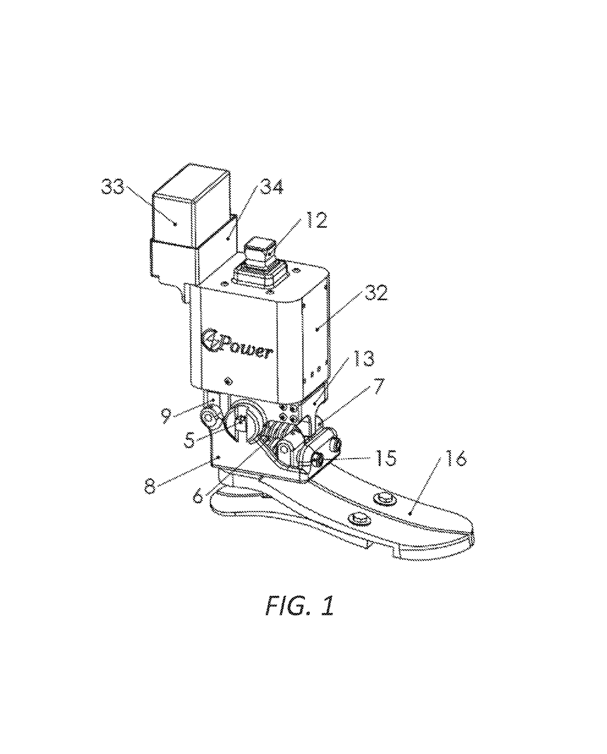
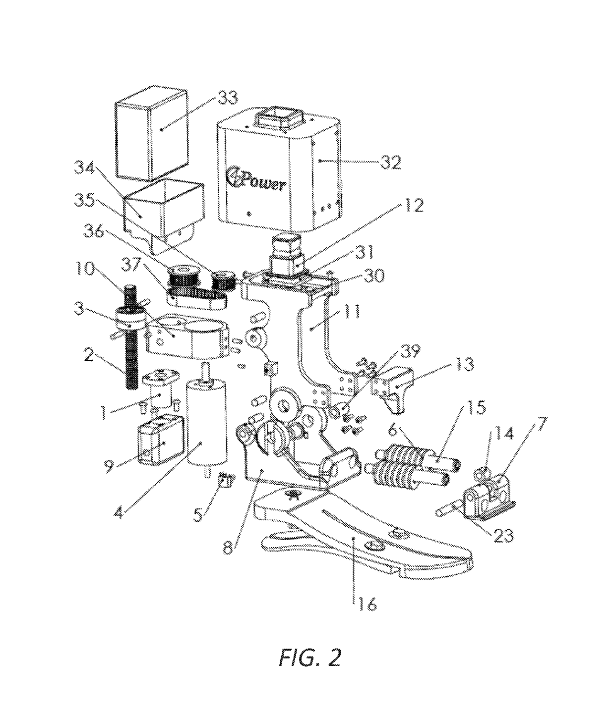
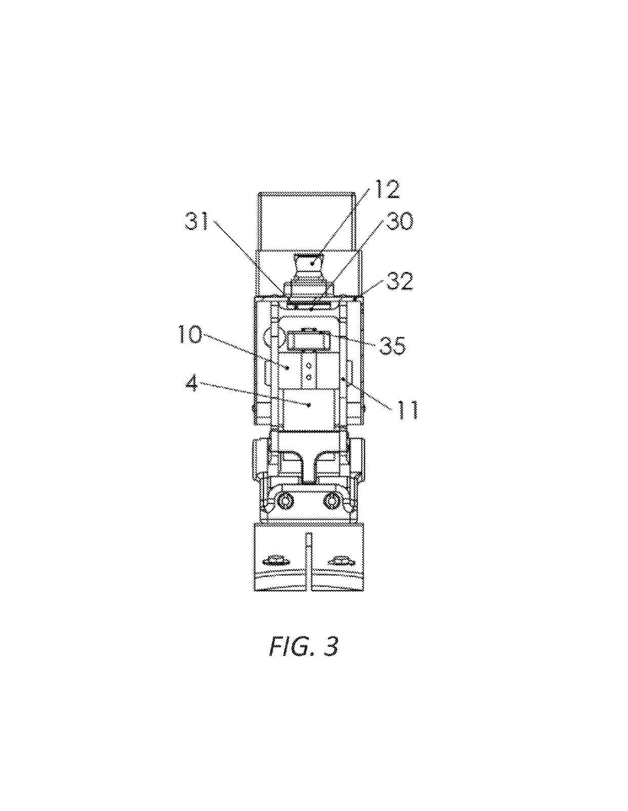
[0022]FIGS. 1-4 shows an embodiment of an ankle-foot prosthesis in accordance with the inventive aspects described herein. An elastic foot 16 is used for shock absorption during a heel-strike portion of a gait. The elastic foot 16 can be embodied as a carbon fiber foot, or any suitable material of sufficient strength and weight for use in an ankle-foot prosthesis. As described herein, elastic foot refers to any type of shock-absorbing foot which can utilize various types of features or mechanisms (e.g. elastomers, spring mechanism, resilient blade, piston, etc.). The ankle-foot prosthesis includes a foot mount 20 for attaching elastic foot 16. Foot mount 20 can include a planar surface with a threaded hol...


PUM


Abstract

A powered ankle-foot prosthesis and associated methods of use are described herein. Such prostheses can employ an actuator and elastic components, the actuator being controlled to deliver net positive work to propel the wearing amputee forward and the elastic components being used to store and release negative energy to improve efficiency. Elastic components can be linear springs coupled with a cam and configured in parallel to the actuator. The cam profile can be designed to generate a desired spring torque versus angle curve rather than a spring stroke versus angle curve, thereby reproducing human ankle controlled dorsiflexion stiffness. Such configurations improve system energy efficiency and reduce both actuator torque and power requirements. Such prostheses can also operate in a passive mode, in which a nearly normal gait can be achieved even without powered assist.

Description

BACKGROUND[0001]Ankle-foot prostheses, also known as transtibial prostheses, are used to help regain walking function in individuals having amputations below the knee. Existing commercial transtibial prostheses generally can be classified into two main types: passive transtibial prostheses and powered transtibial prostheses. As passive transtibial prostheses do not contain actuators, these cannot provide net positive work during a gait cycle, as does an intact human ankle. This lack of positive work hinders amputees from restoring a more natural gait behavior. For some passive prostheses, spring-clutch mechanisms can be used to adjust ankle angle in walking, or improve metabolic walking economy. However, clinical studies showed that due to the inability of passive prostheses to supply net positive work across the stance, transtibial amputees with passive prostheses have various problems during walking, such as non-symmetric gait patterns and higher metabolic cost as compared to the ...

Claims


Application Information

Patent Timeline
Patent Type & Authority Patents(United States)
IPC IPC(8): A61F2/66A61F2/68A61F2/70A61F2/76A61F2/50
CPCA61F2/6607A61F2/66A61F2/68A61F2/70A61F2002/5009A61F2002/7645A61F2002/6664A61F2002/701A61F2002/704A61F2002/7625A61F2002/7635A61F2002/5075A61F2/60A61F2002/6657A61F2002/607A61F2002/6614
Inventor GAO, FEILIU, YAN-NANLIAO, WEI-HSIN
Owner THE CHINESE UNIVERSITY OF HONG KONG
Learn More