Multi-flow-directional filtering device used for range hood

A filtering device and a range hood technology are applied in the fields of removing oil fume, applications, and household stoves, etc., which can solve the problems of less number of changes in direction and insufficient collision of oil fume, and achieve the effect of improving the filtering effect.

Active Publication Date: 2016-09-07
NINGBO FOTILE KITCHEN WARE CO LTD
View PDF7 Cites 10 Cited by
  • Summary
  • Abstract
  • Description
  • Claims
  • Application Information

AI Technical Summary

Problems solved by technology

Although the filter screen can improve the filtering effect by setting the outer rectifying layer and the inner filter layer, but, similar to the existing filter screen, after using the filter screen, the number of times the airflow changes direction when passing through the channel inside the filter screen less, the collision of oil fume in the channel is not sufficient, and the filtering effect needs to be further improved

Method used


Image

  • Multi-flow-directional filtering device used for range hood
  • Multi-flow-directional filtering device used for range hood
  • Multi-flow-directional filtering device used for range hood

Examples


Embodiment 1

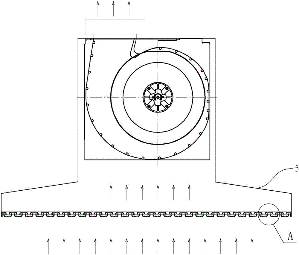
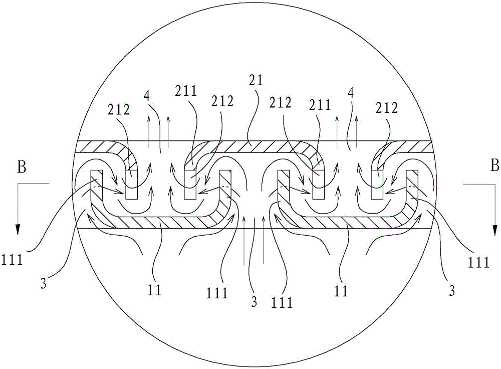
[0029] like Figure 1 to Figure 8 As shown, the multi-flow filter device for a range hood in this embodiment includes a lower filter layer 1 and an upper filter layer 2, such as figure 1 As shown, the filter device is installed horizontally on the hood 5 of the range hood. Figure 4 middle arrow C and Image 6 The direction indicated by the middle arrow D is forward for description.

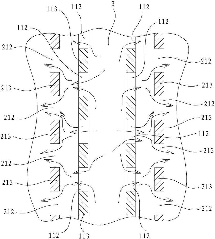
[0030] In this embodiment, the lower filter layer 1 includes a plurality of lower filter units 11 arranged side by side and at intervals, and the gap between two adjacent lower filter units 11 is the soot inflow inlet 3 . The upper filter layer 2 includes a plurality of upper filter units 21 which are arranged side by side at intervals, and the gap between two adjacent upper filter units 21 is the soot outlet 4 . The lower filter unit 11 and the upper filter unit 21 are arranged inversely to each other, and a direction change channel is formed between the lower filter unit 11 and the upper fil...

Embodiment 2

[0037] like Figure 11 As shown, the first gap of the lower filter unit of the filter device in this embodiment and the second gap of the upper filter unit are rectangular gap a, and the rest of the structure and working principle are the same as those in the first embodiment, and will not be expanded here. describe.

Embodiment 3

[0039] like Figure 12 As shown, the first gap of the lower filter unit of the filter device in this embodiment and the second gap of the upper filter unit are the triangular gap b, and the other structures and working principles are the same as those in the first embodiment, and will not be expanded here. describe.


PUM


Abstract

The invention provides a multi-flow-directional filtering device used for a range hood. A lower filtering layer comprises a plurality of lower filtering units which are arranged side by side at intervals in a left and right direction. An upper filtering layer comprises a plurality of upper filtering units which are arranged side by side at intervals in the left and right direction. The lower filtering units and the upper filtering units are arranged in a manner of being oppositely buckled with each other. The multi-flow-directional filtering device is characterized in that the bottoms of the lower filtering units are closed, the two sides of the lower filtering units are provided with first extension walls extending upwards from the bottoms, first notches arranged at intervals in a front and rear direction are formed in the first extension walls, the tops of the upper filtering units are closed, the two sides of the upper filtering units are provided with second extension walls extending downwards from the tops, and second notches arranged at intervals in the front and rear direction are formed in the second extension walls. The multi-flow-directional filtering device has the advantages that after passing the first notches and the second notches, which are arranged on the two side walls of the lower filtering units and the upper filtering units, soot can be turned and collided for multiple times when flows across the filtering device, so that the multi-channel multi-flow-directional filtering of the soot is realized, and the soot filtering effect is effectively improved.

Description

technical field [0001] The present invention relates to a filter device, in particular to a multi-flow filter device for a range hood. Background technique [0002] When the range hood is working, it will inhale a lot of oil fume. The inhaled oil fume will easily accumulate in the air duct to form oil pollution. The oil pollution will not only corrode the pipes, shorten the life of the range hood, but also increase the use and maintenance costs of the range hood. , the existing range hoods are all installed with filter screens for filtering oil fume, and different filter screen structures can produce different oil fume filtering effects. Most of the existing filter nets are of single-layer structure, and filter holes are opened on the filter net body. This kind of filter net structure is relatively simple, and the filtering effect is relatively poor. In order to improve the filtering effect, people have proposed various improved filter net structures, such as "Filter Net an...

Claims


Application Information

Patent Timeline
Patent Type & Authority Applications(China)
IPC IPC(8): F24C15/20
CPCF24C15/2035
Inventor 朱逸施旭娜袁柯铭茅忠群诸永定李斌
Owner NINGBO FOTILE KITCHEN WARE CO LTD
Why Eureka
Try Eureka