Heating pipeline structure and temperature early-warning method

A technology for heating pipes and heating pipes, applied in the field of heating pipe structures and heating devices, can solve problems such as uneven heat dissipation, unreasonable structure, and poor heating effect, so as to improve the efficiency of heat radiation, reduce heat radiation loss, and avoid cold uneven heat effect

Inactive Publication Date: 2016-09-07
WENDENG LANDAO ARCHITECTURAL ENG CO LTD
View PDF0 Cites 1 Cited by
  • Summary
  • Abstract
  • Description
  • Claims
  • Application Information

AI Technical Summary

Problems solved by technology

[0002] It is a complex project to achieve indoor heating with a large number of people in libraries, classrooms, etc., and a large area. Traditional home heating, such as copper-aluminum composite tube heat dissipation, is far from realizing large-area heating, and it is expensive and expensive to use. , and take up a lot of space, the pipes are exposed, very unsightly
Most heating pipes dissipate heat unevenly, resulting in alternation of cold and heat, or local high temperature phenomenon, the heating effect is poor, and the temperature starts slowly, which will cause adverse interference to students' learning and cannot create a comfortable learning atmosphere. It is very difficult to use. Inconvenient, and due to the unreasonable structure, there is a large amount of heat loss in the heating process, resulting in waste of resources and increased user costs, especially uneconomical for large-area heating

Method used


Image

  • Heating pipeline structure and temperature early-warning method
  • Heating pipeline structure and temperature early-warning method
  • Heating pipeline structure and temperature early-warning method

Examples


Embodiment Construction

[0022] The following will clearly and completely describe the technical solutions in the embodiments of the present invention with reference to the accompanying drawings in the embodiments of the present invention. Obviously, the described embodiments are only some, not all, embodiments of the present invention. Based on the embodiments of the present invention, all other embodiments obtained by persons of ordinary skill in the art without making creative efforts belong to the protection scope of the present invention.

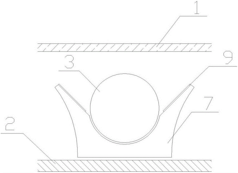
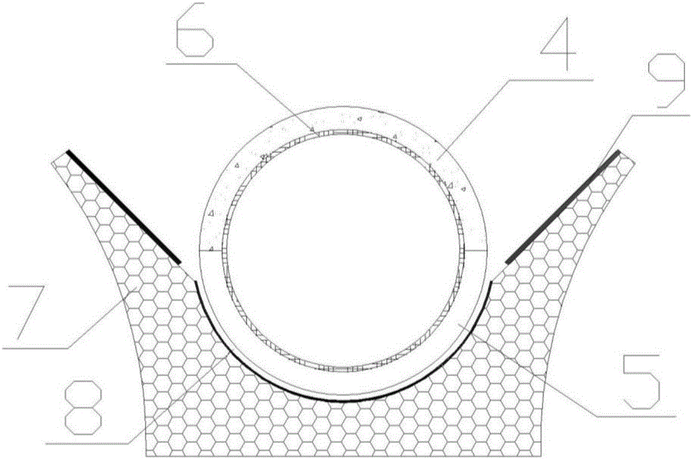
[0023] see Figure 1~2 , a heating pipeline structure, including load-bearing floor 1, foundation 2, heating pipe 3, pipeline a surface 4, pipeline b surface 5, inner protective layer 6, PERT pipe seat 7, installation groove 8 and heat radiation coating 9, the The load-bearing floor 1 is located on the upper part of the heating pipe 3, and there is an air gap between the two. The PERT pipe base 7 is placed on the foundation 2, and its base shape is a plane. Th...


PUM


Abstract

The invention discloses a heating pipeline structure and a temperature early-warning method. The heating pipeline structure comprises a bearing floor, a foundation, a heating pipeline, a pipeline side a, a pipeline side b, an inner protective layer, a PERT pipe seat, a mounting groove and a thermal radiation coating. The heating pipeline structure and the temperature early-warning method have the beneficial effects that the heating pipeline is mounted in the bearing floor, so that space is utilized felicitously, and the heating pipeline is protected from being damage by the external world; the PETR pipe seat is highly heat-proof, and has high heat insulation property; the pipeline side b of the heating pipeline is connected with a mounting groove, so that radiation heat loss to the foundation is greatly reduced; as the pipeline side a is uniformly doped with a heat conduction filling agent, temperature starting can be relatively fast, heat radiation can be uniform, uneven heating is avoided, the environment temperature can be kept agreeable during use, and the thermal radiation effective rate is greatly improved; when the heating pipeline structure and the temperature early-warning method are used in places such as a library and a classroom, a large quantity of heat can be saved, so as to improve the economical applicability of the heating pipeline; and as the inner protective layer is arranged on the inner surface of the pipeline, and the PETR pipe seat is stable, the use reliability of the heating pipeline structure can be guaranteed.

Description

technical field [0001] The invention relates to a heating device and a temperature early warning method based on the heating device, in particular to a heating pipeline structure, which belongs to the field of heating equipment. Background technique [0002] It is a complex project to achieve indoor heating with a large number of people in libraries, classrooms, etc., and a large area. Traditional home heating, such as copper-aluminum composite tube heat dissipation, is far from realizing large-area heating, and it is expensive and expensive to use. , and take up a lot of space, and the pipes are exposed, which is very unsightly. Most heating pipes dissipate heat unevenly, resulting in alternation of cold and heat, or local high temperature phenomenon, the heating effect is poor, and the temperature starts slowly, which will cause adverse interference to students' learning and cannot create a comfortable learning atmosphere. It is very difficult to use. Inconvenient, and du...

Claims


Application Information

Patent Timeline
Patent Type & Authority Applications(China)
IPC IPC(8): F24D19/10F24D3/14
CPCF24D19/1009F24D3/141F24D3/146
Inventor 刘锋刘京林
Owner WENDENG LANDAO ARCHITECTURAL ENG CO LTD
Why Eureka
Try Eureka