Point focusing solar vacuum receiver

A solar concentrator and receiver technology, which is applied to solar thermal collectors, components of solar thermal collectors, mobile/directional solar thermal collectors, etc. requirements and other issues, to achieve the effects of low input cost, simple structure and high concentration ratio

Inactive Publication Date: 2016-09-07
北京金阳科创太阳能技术有限公司
View PDF10 Cites 0 Cited by
  • Summary
  • Abstract
  • Description
  • Claims
  • Application Information

AI Technical Summary

Problems solved by technology

However, most of the existing point-focus receivers are cavity-type, and the convective loss is much greater than the radiation heat loss when used at medium and high temperatures, which greatly affects the thermal efficiency
Therefore, the thermal performance of this non-vacuum cavity receiver still cannot meet the requirements of low-cost medium-temperature collectors in the medium-to-high temperature range.

Method used


Image

  • Point focusing solar vacuum receiver
  • Point focusing solar vacuum receiver
  • Point focusing solar vacuum receiver

Examples


Embodiment 1

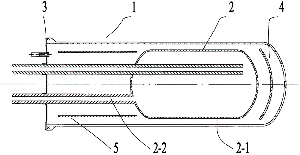
[0031] Example 1, see figure 1 , figure 2 As shown, the present embodiment provides a point-focused solar vacuum receiver, including a glass cover tube 1, a metal heat absorber 2 with an inlet and outlet pipe and an annular vacuum sealing structure 3, the glass cover tube 1 and the belt The metal heat absorber 2 with the inlet and outlet pipes is a single-ended open structure, and the metal heat absorber 2 with the inlet and outlet pipes is arranged at the tail closed end of the glass cover tube 1, and the inlet and outlet of the metal heat absorber 2 with the inlet and outlet pipes The pipe 2-2 is drawn from the single-end opening of the glass cover tube 1, and the annular vacuum sealing structure 3 is sealed between the glass cover tube 1 and the metal heat absorber 2 with the inlet and outlet pipes, and makes it form a vacuum state. The outer surface of the metal heat absorbing body 2-1 is provided with a layer of solar spectrum selective coating. The metal heat absorbi...

Embodiment 2

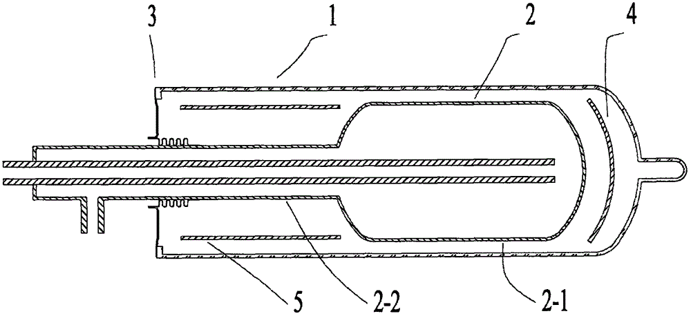
[0032] Example 2, see image 3 , figure 2 As shown, the present embodiment provides a point-focused solar vacuum receiver, including a glass cover tube 1, a metal heat absorber 2 with an inlet and outlet pipe and an annular vacuum sealing structure 3, the glass cover tube 1 and the belt The metal heat absorber 2 with the inlet and outlet pipes is a single-ended open structure, and the metal heat absorber 2 with the inlet and outlet pipes is arranged at the tail closed end of the glass cover tube 1, and the inlet and outlet of the metal heat absorber 2 with the inlet and outlet pipes The pipe 2-2 is drawn from the single-end opening of the glass cover tube 1, and the annular vacuum sealing structure 3 is sealed between the glass cover tube 1 and the metal heat absorber 2 with the inlet and outlet pipes, and makes it form a vacuum state. The outer surface of the metal heat absorbing body 2-1 is provided with a layer of solar spectrum selective coating. The metal heat absorbi...


PUM


Abstract

The invention discloses a point focusing solar vacuum receiver. The point focusing solar vacuum receiver includes a glass casing tube, a metal heat absorbing body with an inlet and outlet pipe, and an annular vacuum sealing structure. Each of the glass casing tube and the metal heat absorbing body with the inlet and outlet pipe is of a single end opening structure; the metal heat absorbing body with the inlet and outlet pipe is arranged at a tail sealing end of the glass casing tube; the inlet and outlet pipe of the metal heat absorbing body leads out from the single end opening structure of the glass casing tube; the annular vacuum sealing structure is sealed between the glass casing tube and the metal heat absorbing body with the inlet and outlet pipe, and forms a vacuum state; the outer surface of the metal heat absorbing body is provided with a solar spectrum selective coating; a radiation insulation board is arranged between a part which cannot receive reflected light of a condenser, of the metal heat absorbing body and the glass casing tube; and a cylindrical thermal insulation board is arranged between the inlet and outlet pipe of the metal heat absorbing body and the glass casing tube. The point focusing solar vacuum receiver can effectively reduce heat loss, can be widely applied to all kinds of point focusing solar rotary condensers, and can provide solar middle-high-temperature thermal collection fields.

Description

technical field [0001] The invention relates to the technical field of solar thermal utilization, in particular to a point-focused solar vacuum receiver. Background technique [0002] The technical field of solar thermal utilization can be divided into three temperature sections according to temperature, low temperature field (40-100°C), medium temperature field (100-300°C), and high temperature field (300-800°C). [0003] The utilization technology in the field of low temperature solar energy is relatively mature, mainly to provide domestic hot water, and its products are flat plate collectors and vacuum tube collectors. At present, the development trend of photothermal applications is shifting to the field of medium temperature industrial and agricultural applications and the field of high temperature thermal power generation. Especially in heating, refrigeration and air conditioning, industrial heating and other medium-temperature applications, there is a wide and urgent...

Claims


Application Information

Patent Timeline
Patent Type & Authority Applications(China)
IPC IPC(8): F24J2/05F24J2/54F24J2/48F24J2/12F24S10/40F24S23/71
CPCF24S10/40F24S23/71F24S30/428F24S70/12F24S70/20Y02E10/44Y02E10/47
Inventor 蒋富林孙伟高汉三葛洪川
Owner 北京金阳科创太阳能技术有限公司
Why Eureka
Try Eureka