
Optical measuring method of strain rate field in plane of object

An optical measurement and strain rate technology, applied in measurement devices, optical devices, instruments, etc., can solve the problems of complex mathematical form and programming execution, large error in strain calculation results, unfavorable promotion and application, etc., to improve the accuracy and The effect of reliability, easy programming, and simple and convenient calculation process

Inactive Publication Date: 2016-09-07
LIAONING TECHNICAL UNIVERSITY
View PDF5 Cites 4 Cited by
  • Summary
  • Abstract
  • Description
  • Claims
  • Application Information

AI Technical Summary

Problems solved by technology

[0005] Using the digital image correlation method, the deformation measurement method in the object plane mainly includes: 1) The digital image correlation method based on the Newton-Raphson (N-R) method can obtain the displacement and strain in the object plane at the same time, but the error of the strain calculation result is relatively small. 2) The digital image correlation method based on the central difference method obtains the strain field by taking the central difference of the displacement field, but the noise contained in the displacement field will reduce the credibility of the strain calculation results; 3) Based on finite element smoothing The digital image correlation method of the method uses the finite element method to smooth the displacement field to obtain the strain field, but the mathematical form and programming execution are complicated, which is not conducive to popularization and application

Method used


Image

  • Optical measuring method of strain rate field in plane of object
  • Optical measuring method of strain rate field in plane of object
  • Optical measuring method of strain rate field in plane of object

Examples


Embodiment Construction

[0031] An embodiment of the present invention will be further described below in conjunction with the accompanying drawings.

[0032] The embodiment of the present invention measures the strain rate field on the surface of the test piece during the uniaxial compression process;

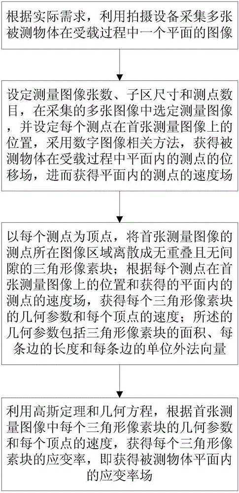
[0033] In the embodiment of the present invention, an optical measurement method of the strain rate field in the object plane, the method flow chart is as follows figure 1 shown, including the following steps:

[0034] Step 1. According to actual needs, use the shooting device to collect multiple images of a plane of the object under load during loading;

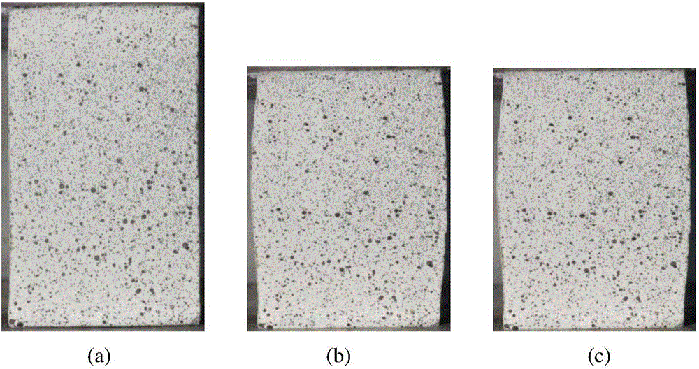
[0035] In the embodiment of the present invention, the object to be tested is a rectangular parallelepiped specimen with a height of 85.51mm and a width of 53.02mm. The specimen is placed on a platform, and artificial speckle is made with paint on one surface of the specimen. Displacement-controlled loading to collect speckle patterns of the surfa...


PUM


Abstract

The invention relates to an optical measuring method of a strain rate field in the plane of an object and belongs to the object strain rate field measurement technical field. The method includes the following steps that: a photographing device is utilized to photograph a plurality of images of one plane of a measured object in a loaded process; measurement images are selected, and the number of the measurement images, sub area size and the number of measuring points are set; the measuring points are dispersed in an image area so as to form non-overlapping and gapless triangular pixel blocks; and a strain rate field in the plane of the measured object is obtained by using Gauss theorem and a geometric equation. The method of the invention is superior to a central difference method-based digital image correlation method. The calculation process of the method of the invention is simple and convenient, only summation calculation is required, so that a result can be obtained; the implementation of programming is easy; and accuracy and reliability can be improved. The optical measuring method has a broad application prospect in the solid experimental mechanics field.

Description

technical field [0001] The invention belongs to the technical field of object strain rate field measurement, and in particular relates to an optical measurement method of the strain rate field in an object plane. Background technique [0002] Object deformation measurement is an important part of experimental mechanics; compared with other measurement methods, optical measurement methods play an irreplaceable role in experimental mechanics due to their advantages of non-contact, full-field, high spatial resolution and high measurement accuracy. ; In practical applications, object deformation measurement often refers to the measurement of deformation in the object plane. [0003] The digital image correlation method is an important method in the optical measurement method, which is to correlate two images (speckle fields) of the object surface collected before and after the deformation, so as to realize the deformation measurement of the object; Deformation measurement, out-...

Claims


Application Information

Patent Timeline
IPC IPC(8): G01B11/16
CPCG01B11/16
Inventor 王学滨武其奡冯威武马冰白雪元齐大雷
Owner LIAONING TECHNICAL UNIVERSITY
Learn More