
CAN (Controller Area Network) bus remote monitoring system based on electric heat tracing liquid indicator

A remote monitoring system and CAN bus technology, applied in the field of liquid level gauges, can solve the problems of not being able to understand the liquid level of on-site equipment in real time, making it difficult to ensure safe and reliable operation of production, and not having remote monitoring functions, etc., to achieve flexible and convenient control methods, Stable and reliable performance, the effect of reducing production costs

Inactive Publication Date: 2016-09-07
TIANJIN XINCHENG INSTR & METER PLANT
View PDF4 Cites 0 Cited by
  • Summary
  • Abstract
  • Description
  • Claims
  • Application Information

AI Technical Summary

Problems solved by technology

Existing heat-retaining liquid level gauges usually have a steam jacket type and a hot water tracing type. In order to realize the above working methods, facilities such as boilers and pipelines must be installed, which greatly increases the production cost; in addition, the existing liquid level gauges usually Without remote monitoring function, it is impossible to know the liquid level of on-site equipment in real time, and it is difficult to ensure safe and reliable operation of production

Method used


Image

  • CAN (Controller Area Network) bus remote monitoring system based on electric heat tracing liquid indicator
  • CAN (Controller Area Network) bus remote monitoring system based on electric heat tracing liquid indicator
  • CAN (Controller Area Network) bus remote monitoring system based on electric heat tracing liquid indicator

Examples


Embodiment Construction

[0016] Embodiments of the present invention are described in further detail below in conjunction with the accompanying drawings:

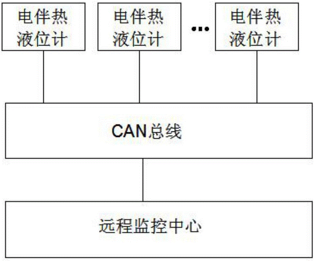
[0017] A CAN bus remote monitoring system based on electric heating liquid level gauge, such as figure 1 As shown, including electric heat tracing level gauges installed on different field devices, CAN bus and remote monitoring center, multiple electric heat tracing level gauges are connected to the remote monitoring center through CAN bus, this electric heat tracing level gauge The monitoring data is transmitted by connecting with the remote monitoring center through the CAN bus, and the remote monitoring center can also send control commands to the electric heating level gauge to control the work of the electric heating level gauge in real time. This monitoring system adopts the CAN bus mode in the existing system, which can avoid the capital investment brought by the construction of the communication network.

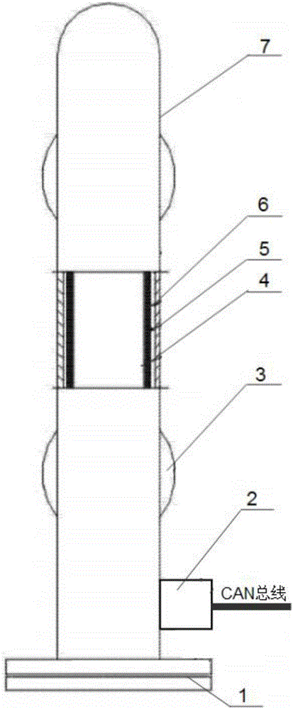
[0018] like figure 2 As shown, ...


PUM


Abstract

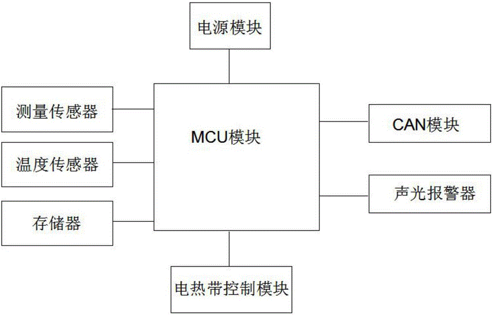
The invention relates to a CAN (Controller Area Network) bus remote monitoring system based on an electric heat tracing liquid indicator. The CANbus remote monitoring system based on the electric heat tracing liquid indicator is technically characterized by comprising the electric heat tracing liquid indicator, a CAN bus and a remote monitoring center. The electric heat tracing liquid indicator comprises a sealing flange, an electronic control device, a connecting flange, a measuring cylinder, an electric heat tape, an insulating layer and a protective housing; the electronic control device comprise an MCU (Microprogrammed Control Unit) module, a power module, a measuring sensor, a temperature sensor, a CAN module, an audible and visual alarm module and an electric heat tape control module; the MCU module is respectively connected with the measuring sensor, the temperature sensor, the electric heat tape control module, an audible and visual alarm and the CAN module; the electric heat tape control module is connected with the electric heat tape; the CAN module is connected with the remote monitoring center through the CAN bus to realize a remote monitoring function. According to the CANbus remote monitoring system based on the electric heat tracing liquid indicator provided by the invention, the on-site liquid indicator is connected with the remote monitoring center throughthe CAN bus, so that remote monitoring personnel can remotely monitor the liquid indictor anytime anywhere, and the control mode is flexible and convenient.

Description

technical field [0001] The invention belongs to the technical field of liquid level gauges, in particular to a CAN bus remote monitoring system based on electric heat tracing liquid level gauges. Background technique [0002] At present, in the process of petroleum, chemical and other industrial production, the measured medium needs a certain temperature protection, especially in the northern winter when the outdoor temperature is very low, and the liquid level gauge must be insulated to ensure the temperature of the liquid level gauge when working outdoors. normal work. Existing heat-retaining liquid level gauges usually have a steam jacket type and a hot water heating type. In order to realize the above working methods, facilities such as boilers and pipelines must be installed, which greatly increases the production cost; in addition, the existing liquid level gauges usually Without remote monitoring function, it is impossible to know the liquid level of on-site equipmen...

Claims


Application Information

Patent Timeline
Patent Type & Authority Applications(China)
IPC IPC(8): G01F23/00G05B19/048
CPCG01F23/00G05B19/048
Inventor 何桂春李智
Owner TIANJIN XINCHENG INSTR & METER PLANT
Learn More