Flexible hair sensor based on ferromagnetic microfilaments and applications thereof

A sensor and microwire technology, applied in the sensor field, can solve the problems of limited application field, complex structure, inability to directly test contact stress or vibration, etc., to achieve high sensitivity and stability, excellent mechanical properties, cyclability and corrosion resistance. strong effect

Active Publication Date: 2016-09-07
HARBIN INST OF TECH
View PDF4 Cites 8 Cited by
  • Summary
  • Abstract
  • Description
  • Claims
  • Application Information

AI Technical Summary

Problems solved by technology

[0008] The purpose of the present invention is to solve the problem that the existing hair sensor generally has a rigid structure, its structure is relatively complicated, and its application field is limited. It can only test the non-contact flow velocity, but cannot directly test the contact stress or vibration. Magnetic Microwire Flexible Sweat Hair Sensor and Its Application

Method used


Image

  • Flexible hair sensor based on ferromagnetic microfilaments and applications thereof
  • Flexible hair sensor based on ferromagnetic microfilaments and applications thereof
  • Flexible hair sensor based on ferromagnetic microfilaments and applications thereof

Examples


specific Embodiment approach 1

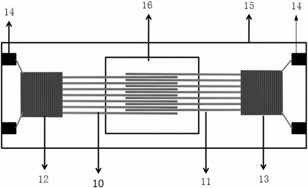
[0022] Embodiment 1: The flexible hair sensor based on ferromagnetic microwires in this embodiment includes a plurality of ferromagnetic microwires, a coil and a substrate 15, and the plurality of ferromagnetic microwires are respectively arranged in parallel and at intervals to form the first ferromagnetic microwire array 10 and The second ferromagnetic microwire array 11, one end of the first ferromagnetic microwire array 10 and one end of the second ferromagnetic microwire array 11 are arranged to cross each other and suspended, at the other end of the first ferromagnetic microwire array 10 A coil with an alternating current signal is wound on it as the excitation end 12, and the other end of the second ferromagnetic microwire array 11 is wound with a coil as the detection end 13, and the first ferromagnetic microwire array 10 is wound with one end of the coil and One end of the second ferromagnetic microwire array 11 wound with a coil is fixed on the substrate 15 .

[0023...

specific Embodiment approach 2

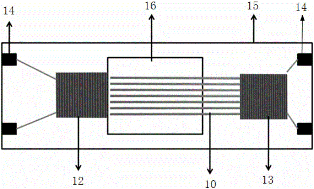
[0026] Embodiment 2: The flexible hair sensor based on ferromagnetic microwires in this embodiment includes a plurality of ferromagnetic microwires, a coil and a substrate 15, and a plurality of ferromagnetic microwires are arranged in parallel to form a ferromagnetic microwire array 10, which is supplied with an alternating current. The coil of the signal is used as the excitation terminal 12, and one end of the ferromagnetic microwire array 10 is suspended in the air and has a gap with the excitation terminal 12, and a coil is wound on the other end of the ferromagnetic microwire array 10 as the detection terminal 13, and the ferromagnetic microwire array One end of 10 wound with a coil is fixed on the base plate 15 .

[0027] The ferromagnetic microwires in the ferromagnetic microwire array of this embodiment can be arranged closely or spaced apart from each other. The space for the ferromagnetic microwire array to move freely is given by the setting of the gap.

specific Embodiment approach 3

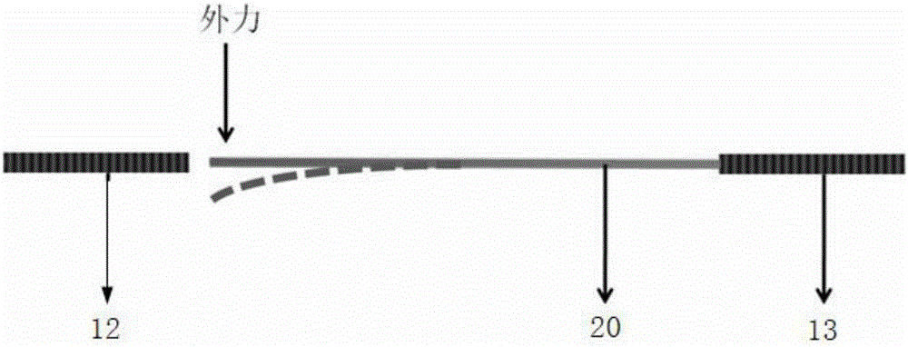
[0028] Specific embodiment three: the flexible hair sensor based on ferromagnetic microwire in this embodiment comprises a single ferromagnetic microwire 20 and a coil. There is a gap with the excitation end 12 , and a coil is wound on the other end of the single ferromagnetic microwire 20 as the detection end 13 .

[0029] In this embodiment, the space for the ferromagnetic microwire array to move freely is provided by setting the gap.


PUM


Abstract

The invention discloses a flexible hair sensor based on ferromagnetic microfilaments and applications thereof, and belongs to the field of sensors. The invention aims to solve the problem of current hair sensors that current hair sensors often have rigid and complex structures and also have limited application fields that the current hair sensors can only test non-contact flow velocity and can not conduct direct test on contact stress or vibration. The flexible hair sensor includes ferromagnetic microfilaments and coils, wherein the ferromagnetic microfilaments serve as a flexible sensing unit the structure of which is composed of two rows of ferromagnetic microfilament arrays which are in crossed arrangement and two coils. The two coils are wound around the distal ends of the ferromagnetic microfilament arrays with a certain number of turns, one coil serving as an excitation end and the other coil serving as a detection end. According to the invention, the flexible hair sensor adopts the sensing theory of electromagnetic induction in testing deformation occurred to the ferromagnetic microfilaments, has high sensitivity and adjustable measuring range. For the detection of external signals, the flexible hair sensor can realize adjustment of sensitivity and measuring range, can be widely applied to the detection of gas wind speed, liquid flow velocity and vibration signal, and has great potential.

Description

technical field [0001] The invention belongs to the field of sensors, in particular to a flexible hair sensor based on ferromagnetic microwires and its application. Background technique [0002] The hair sensor is a sensor derived from the bionic tentacles structure. The tentacles of animals in nature can be very sensitive to external stimuli, such as wind speed, water speed, vibration, contact, etc. External signals, based on this principle, a series of Hair sensor, but different from animal tentacles in nature, the hairs of existing hair sensors are rigid and cannot be deflected at a large angle. They can only be limited to the measurement of gas flow velocity, and cannot test fluid flow velocity or vibration signals. Most of them are based on micro-electro-mechanical system (MEMS) technology, the structure is relatively complex and fragile, and they cannot be as durable as real hair and sense various signals, making the use range of existing hair sensors very narrow and c...

Claims


Application Information

Patent Timeline
Patent Type & Authority Applications(China)
IPC IPC(8): G01P5/08G01H11/02
CPCG01P5/086G01P11/02
Inventor 郝立峰张健王荣国赫晓东
Owner HARBIN INST OF TECH
Why Eureka
Try Eureka