
Phononic crystal axes of a discretized rubber layer with low-frequency vibration-damping properties

A technology of phononic crystals and rubber layers, which is applied in the direction of sound-generating devices and instruments, and can solve problems such as difficult engineering applications and single adjustment methods

Inactive Publication Date: 2018-12-04
XI'AN UNIVERSITY OF ARCHITECTURE AND TECHNOLOGY
View PDF5 Cites 0 Cited by
  • Summary
  • Abstract
  • Description
  • Claims
  • Application Information

AI Technical Summary

Problems solved by technology

Moreover, the band gap is relatively high (200-1000HZ), and a local resonance structure with a relatively large weight must be added to obtain a low-frequency band gap, which increases the difficulty of engineering application, and can only isolate torsional vibration, and the adjustment method is very simple

Method used


Image

  • Phononic crystal axes of a discretized rubber layer with low-frequency vibration-damping properties
  • Phononic crystal axes of a discretized rubber layer with low-frequency vibration-damping properties
  • Phononic crystal axes of a discretized rubber layer with low-frequency vibration-damping properties

Examples


Embodiment 1

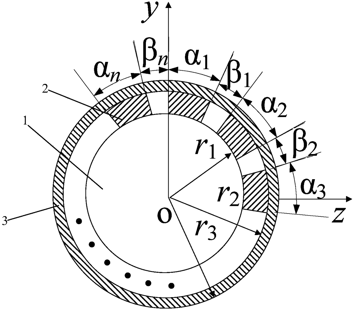
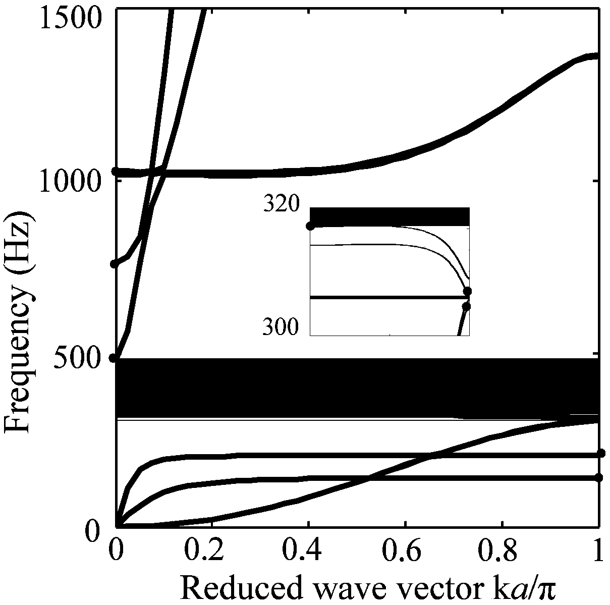
[0027] n=3, α 1 =α 2 =α 3 = Β 1 = Β 2 = Β 3 = 60°, in the range of 0-1500HZ, there are two complete band gaps, such as image 3 Shown. The first complete band gap: 308.7-309.4 Hz, and the second complete band gap 325.7-487.6 Hz. Flexural wave band gap: 321Hz-1018Hz, torsional wave band gap 142Hz-763Hz, longitudinal wave band gap 206Hz-488Hz.

[0028] Figure 4 It is the energy band diagram of the traditional phononic crystal axis. It can be seen that there are two complete band gaps at 0-1500 Hz, the first complete band gap is 357.6-442 kHz, the second complete band gap is 484.5-672.8 Hz. Flexural wave band gap 357.5-442Hz and 484-1438Hz, torsion wave band gap 197to1018Hz, longitudinal wave band gap 270-680Hz.

Embodiment 2

[0030] n=3, α 1 = 30°, α 2 = 60°, α 3 =90°, β 1 = Β 2 = Β 3 = 60°, in the range of 0-1500HZ, there are two complete band gaps. The first complete band gap: 330-350 Hz, the second complete band gap 369-502 Hz. Flexural wave band gap: 330Hz-350Hz, 369-870Hz, torsion wave band gap 142Hz-754Hz, longitudinal wave band gap 209Hz-502Hz.

Embodiment 3

[0032] n=3, α 1 =α 2 =α 3 = 10°, β 1 = Β 2 = Β 3 =110°, the lowest band gap of the bending wave is from 128.6 to 319HZ, the lowest energy band gap of the longitudinal wave is from 84-201HZ, and the three elastic wave band gaps are the lowest. The lowest energy band gap of the torsion wave is from 44 to 245HZ. For the complete band gap, the lowest is from 128.6 to 201HZ.

[0033] It can be seen that the structure of the present invention can make:

[0034] 1. Band gap decreases

[0035] The introduction of the discrete rubber layer reduces the first complete band gap of the new structure and the width decreases to a state of almost disappearing, and the second band gap decreases. The discretization of the rubber layer has a greater impact on the bending wave, causing the first band gap of the bending wave to disappear and the second band gap to move down; while the band gaps of the torsional wave and the longitudinal wave show a downward trend, and the shape of the dispersion curve ...


PUM


Abstract

A phonon crystal shaft with a discretized rubber layer with low-frequency vibration damping characteristics, including a shaft base, a number of periodically distributed rubber layers are arranged outside the shaft base along its axial direction, and there are scatterers outside the rubber layer, each A section of rubber layer is composed of multiple discrete circular arc rubber sections. The phononic crystal axis of the present invention has a lower bandgap characteristic than the traditional phononic crystal axis, and has a controllable bandgap range for the three elastic waves; its The band gap can also be adjusted by adjusting the angle and number of rubber arcs; and, when the number of rubber arcs remains constant and the angle of each rubber arc decreases, the first complete band gap tends to disappear; this The invention of the phononic crystal shaft has potential applications in precision mechanical engineering to control the low-frequency vibrations of drive shafts.

Description

Technical field [0001] The invention belongs to the technical field of functional materials, and particularly relates to a phononic crystal shaft of a discretized rubber layer with low-frequency vibration damping characteristics. Background technique [0002] Phononic crystal is a new type of artificial structure and functional material. Through design, the transmission of elastic waves can be adjusted artificially, and the propagation of elastic waves is prohibited within the band gap frequency. Phononic crystals have been widely used to isolate noise and vibration, mechanical filters and still waveguides. [0003] Currently, there are two completely different band gap mechanisms in phononic crystals, namely the Bragg band gap mechanism and the local resonance mechanism. In the Bragg band gap mechanism, the lattice constant of the phononic crystal is the same order of magnitude as the band gap wavelength of the base material, which limits the lattice size of the phononic crystal....

Claims


Application Information

Patent Timeline
Patent Type & Authority Patents(China)
IPC IPC(8): G10K11/162
CPCG10K11/162
Inventor 李丽霞蔡安江解妙霞
Owner XI'AN UNIVERSITY OF ARCHITECTURE AND TECHNOLOGY
Learn More