Linear generator primary

A linear generator, primary technology, applied in the direction of electrical components, electromechanical devices, etc., can solve problems such as power mismatch of linear generators, and achieve the effects of overcoming low generator efficiency, increasing length, and high operating efficiency

Active Publication Date: 2016-09-07
INST OF ELECTRICAL ENG CHINESE ACAD OF SCI
View PDF4 Cites 12 Cited by
  • Summary
  • Abstract
  • Description
  • Claims
  • Application Information

AI Technical Summary

Problems solved by technology

[0004] The purpose of the present invention is to overcome the shortcomings of the power mismatch of the linear generator in the existing point-absorbing direct-drive wave energy generation system, and propose a linear generator with a short primary and long secondary linear generator.

Method used


Image

  • Linear generator primary
  • Linear generator primary
  • Linear generator primary

Examples


Embodiment 1

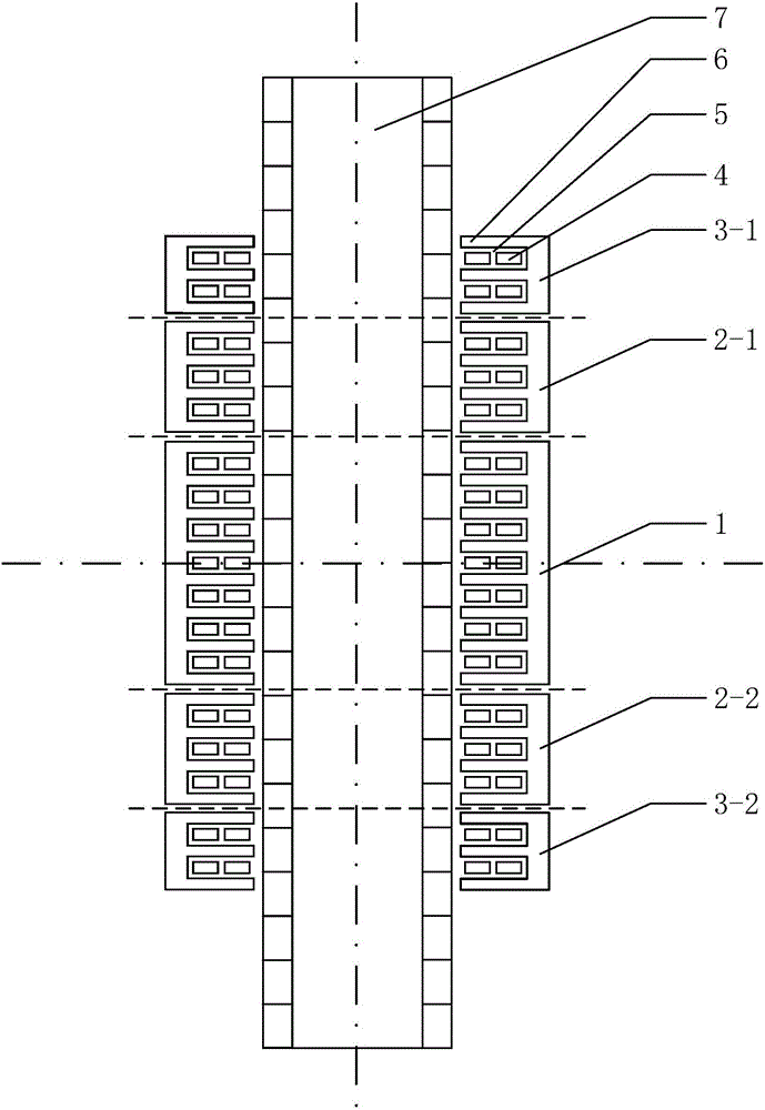
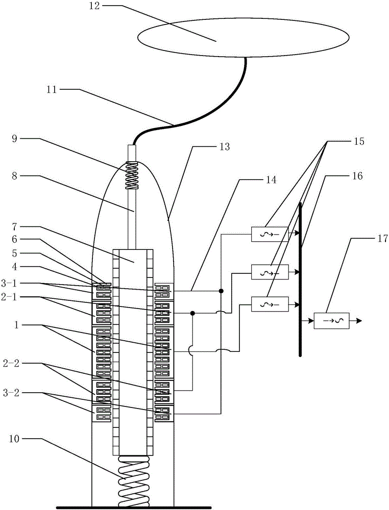
[0022] The primary stage of the linear generator of the present invention can be used in a direct-drive wave energy power generation system fixed on the seabed, figure 2 Shown is Embodiment 1: a direct-drive point-absorption wave energy power generation system with the bottom fixed on the seabed. Such as figure 2 As shown, the motor casing 13 is fixed on the seabed of the seabed, and the floating buoy 12 floats on the sea surface. The two second-stage primary units 2-1 and 2-2 of the linear generator are respectively located on the upper and lower sides of the first-stage primary unit 1, and the first and third-stage primary units 3-1 are located at the first and second-stage primary unit 2 On the upper side of -1, the second and third stage primary unit 3 - 2 is located on the lower side of the second second stage primary unit 2 - 2 , and is integrally fixed on the inside of the motor casing 13 . The primary winding 4 can be concentrated winding or distributed winding or ...

Embodiment 2

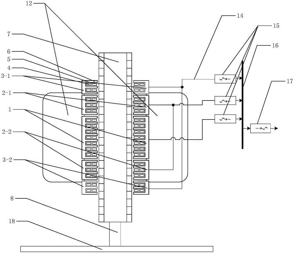
[0027] The primary stage of the linear generator of the present invention can be used in a double-float floating direct-drive type point-absorbing wave energy power generation system. image 3 Shown is Embodiment 2: a double-float floating direct-drive point-absorption wave energy power generation system. Such as image 3 As shown, the power generation system as a whole floats on the sea surface, and the floating buoy 10 floats on the sea surface, such as image 3 As shown, the two-stage second-stage primary units 2-1 and 2-2 of the linear motor are respectively located on the upper and lower sides of the first-stage primary unit 1, and the first and third-stage primary units 3-1 are located on the first and second-stage primary units. On the upper side of the unit 2-1, the second and third primary unit 3-2 is located on the lower side of the second second linear unit 2-2, and is integrally fixed on the inner side of the floating buoy 10. The primary winding 4 can adopt conc...


PUM


Abstract

Disclosed is a linear generator primary. The linear generator primary comprises a sectional type primary stator core and a sectional type primary winding, wherein the primary stator core and the primary winding are segmented in a vertical direction so as to form multiple primary stator core units and primary winding units. Primary stator wire ducts (6) are arranged at uniform intervals at one side, facing a secondary, of each primary stator core unit, each primary winding unit is embedded in the primary stator wire ducts (6) of the corresponding primary stator core unit so as to form a primary unit. Projection portions between adjacent primary stator wire ducts (6) are primary stator teeth (5). The length of the primary unit disposed at the center of the secondary is the longest, and the length of the primary unit distanced furthest from the center of the secondary is the shortest. Two primary winding units symmetrically arranged along the center of the secondary control on-off through one electric and electronic device. The linear generator primary can be applied to a point absorption direct-driven wave energy power generation system.

Description

technical field [0001] The invention relates to the technical field of wave energy power generation, in particular to a long secondary and short primary linear generator applied to a direct-drive point absorption wave energy power generation system. Background technique [0002] The point absorption wave energy power generation system refers to a power generation system in which the size of the floating buoy used to capture energy is much smaller than the wavelength of the wave. The system can usually be divided into direct drive type and non-direct drive type. In non-direct drive systems, the float is connected to a speed increasing device such as a pneumatic system, a hydraulic system or a gearbox, and then connected to a rotating generator. The non-direct drive system is small in size, but its intermediate links are complicated, which reduces the reliability and conversion efficiency of the system. The direct drive system floats are directly connected to the linear gener...

Claims


Application Information

Patent Timeline
Patent Type & Authority Applications(China)
IPC IPC(8): H02K35/02
CPCH02K35/02
Inventor 王海峰邱书恒艾程柳黄元峰徐松
Owner INST OF ELECTRICAL ENG CHINESE ACAD OF SCI
Why Eureka
Try Eureka