Flange packaging structure provided with electric heating pipes

A technology of packaging structure and electric heating tube, applied in the direction of ohmic resistance heating parts, heating elements, etc., can solve the problems of affecting the firmness of the connection, easy to rust, easy to rust and loosen the nut, etc., to achieve good sealing, not easy to Rust, good firmness effect

Active Publication Date: 2016-09-07
PINGHU CANNET ELECTRIC APPLIANCE TECH
View PDF18 Cites 2 Cited by
  • Summary
  • Abstract
  • Description
  • Claims
  • Application Information

AI Technical Summary

Problems solved by technology

[0002] In the prior art, the flange installation of the electric heating tube is to pass the electric heating tube and install it on the horizontal flange surface. Pass through the gap between the two, then use the connecting piece to connect the two electric heating tube lead rods, and then use two nuts to fix the connecting piece and the two lead rods (or do not use the connecting piece, directly each lead rod Fix it with a nut), the nut is easy to rust and loosen after a long time of use, affecting the firmness of the connection
The gap between the electric heating tube and the flange of this structure is also prone to rust; the sealing ring is set on the periphery of the heating tube by its own friction and is not fixed. The sealing ring extends into the heating water cavity, and it is easy to accumulate impurities such as scale, and The distance from the heating tube is also susceptible to rust, which in turn affects the sanitation of the drinking water heated by the electric heating tube. There is a flange mounting hole near the edge of the flange, and the mounting hole is also prone to water seepage, affecting hygiene and installation. The tightness will affect the service life of the electric heating tube and the flange, and it is also not conducive to the health and sanitation of people's drinking water.

Method used


Image

  • Flange packaging structure provided with electric heating pipes
  • Flange packaging structure provided with electric heating pipes

Examples


Embodiment Construction

[0020] The technical solutions of the present invention will be further described and illustrated through specific examples below.

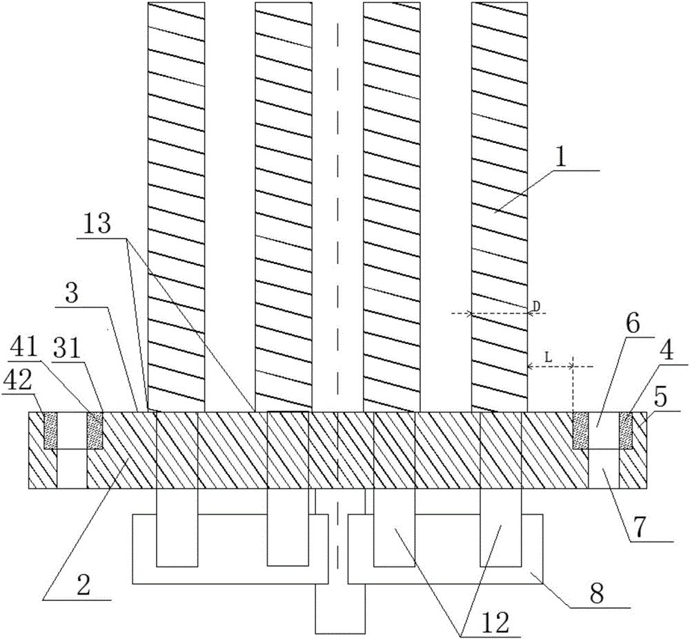
[0021] Such as figure 1 As shown, a flange package structure for installing electric heating tubes is provided with a raised surface 3 on the upper end surface of the flange plate 2, the electric heating tube 1 is installed on the raised surface, and a sealing ring 4 is sleeved on the periphery of the raised surface (also is the gasket), the sealing ring can have a first through hole 6, and the flange is provided with a second through hole 7 corresponding to the position of the first through hole, and the first through hole and the second through hole can be connected by a fastener The flange connection on the heating device (such as a water heating chamber) using the flange packaging structure improves the sealing performance and avoids water seepage caused by traditional installation.

[0022] The connection between the end portion 13 of the e...


PUM


Abstract

The invention discloses a flange packaging structure provided with electric heating pipes. The flange packaging structure comprises the electric heating pipes, and also comprises a flange plate and seal rings, wherein a raised surface is arranged at the middle portion of the flange plate, the electric heating pipes are arranged on the raised surface, the seal rings are arranged at the periphery of the raised surface and provided with first through holes, and the flange plate is provided with second through holes corresponding to the through holes. According to the structure of the device, the problems that when drinking water is heating, the existing installation of the electric heating pipe and the flange may cause a health problem, and the flange is prone to contact the water to rust and corrode are solved.

Description

technical field [0001] The invention belongs to the field of heating tubes of water dispensers, and in particular relates to a flange packaging structure for installing electric heating tubes. Background technique [0002] In the prior art, the flange installation of the electric heating tube is to pass the electric heating tube and install it on the horizontal flange surface. Pass through the gap between the two, then use the connecting piece to connect the two electric heating tube lead rods, and then use two nuts to fix the connecting piece and the two lead rods (or do not use the connecting piece, directly each lead rod Fix it with a nut), the nut is easy to rust and loosen after a long time of use, affecting the firmness of the connection. The gap between the electric heating tube and the flange of this structure is also prone to rust; the sealing ring is set on the periphery of the heating tube by its own friction and is not fixed. The sealing ring extends into the he...

Claims


Application Information

Patent Timeline
Patent Type & Authority Applications(China)
IPC IPC(8): H05B3/06
CPCH05B3/06
Inventor 马园飞
Owner PINGHU CANNET ELECTRIC APPLIANCE TECH
Why Eureka
Try Eureka