
Front cover structure of automatic two wheel vehicle

A technology for automatic two-wheeled vehicles and front covers, applied to bicycle accessories, weather guards, transportation and packaging, etc., can solve the problems of not being able to play the rectification of driving wind, and achieve the effect of good flow and stable flow

Active Publication Date: 2016-09-14
HONDA MOTOR CO LTD
View PDF10 Cites 4 Cited by
  • Summary
  • Abstract
  • Description
  • Claims
  • Application Information

AI Technical Summary

Problems solved by technology

Therefore, there is a problem in that only by providing openings, effects such as smooth flow of traveling wind and rectification cannot be exhibited.

Method used


Image

  • Front cover structure of automatic two wheel vehicle
  • Front cover structure of automatic two wheel vehicle
  • Front cover structure of automatic two wheel vehicle

Examples


Embodiment Construction

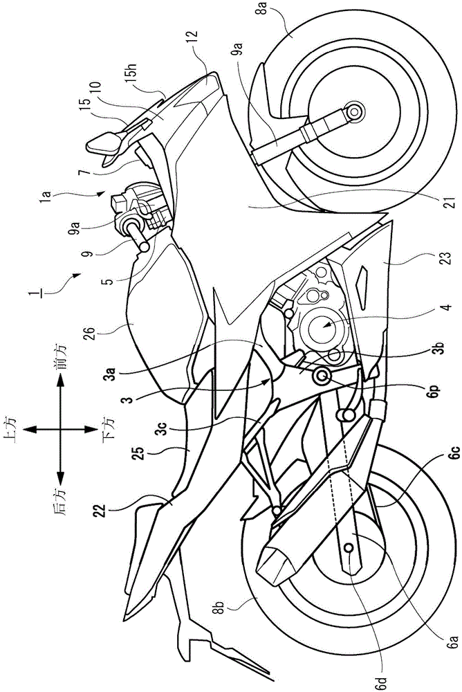
[0050] Below, refer to Figure 1 to Figure 10 A motorcycle according to an embodiment of the present invention will be described. In addition, regarding the direction of the symbols in the drawings, in the following description, front and rear, left and right, and up and down are described along the direction viewed from the operator, and the front of the vehicle in the drawings is represented by Fr, and the rear is represented by Fr. Rr represents, the left side is represented by L, the right side is represented by R, the top is represented by U, and the bottom is represented by D. In addition, the same expression is used also in description about the direction of each component of a motorcycle.

[0051] Such as figure 1 As shown, the vehicle body frame 3 as the skeleton part of the motorcycle 1 has the following components: a pivot plate 3b located on the rear side of the engine 4, and a head pipe 5 directed from the pivot plate 3b toward the vehicle front portion 1a. A m...


PUM


Abstract

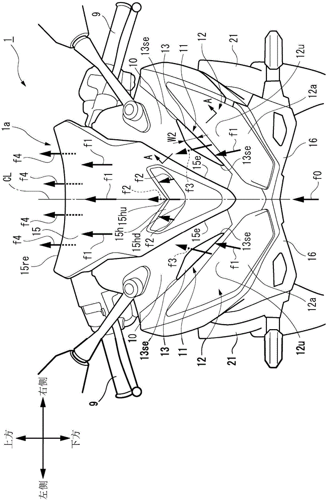
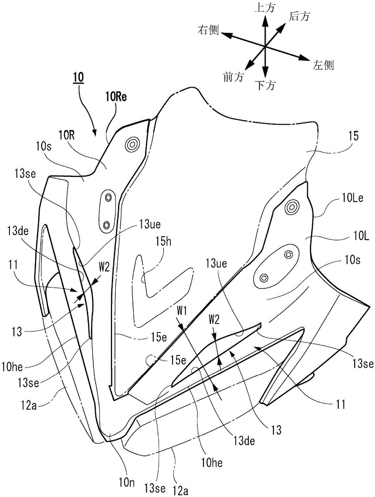
The invention provides a front cover structure of an automatic two wheel vehicle. The front cover structure enables smooth flow of air on the front cover arranged on the front part of the vehicle. The front cover structure of the automatic two wheel vehicle (1) includes a head lamp 912) arranged on the front part of the vehicle, a front cvoer (10) arranged in a manner of surrounding the outer periphery of the head lamp (12), a protection shade (15) arranged on the upper side of the front cover (10). The front cover structure is characterized in that a concave part (11) sinking towards the inner side of the vehicle is formed in the front cover and between the head lamp (12) and the protection shade (15) and an opening enabling drive air to flow into the front cover is fromed in the concave part (11).

Description

technical field [0001] The present invention relates to a motorcycle, and in particular, to a front cover structure of a motorcycle provided at the front of the vehicle. Background technique [0002] In the front cover structure of the existing motorcycle, for example, there is the following structure: as described in Patent Document 1, a curved surface is formed as the main body, and an opening for allowing the running wind to enter is provided on the front portion thereof, and the air flow from the opening is formed. The incoming driving air flows to the side of the intake system. [0003] prior art literature [0004] patent documents [0005] Patent Document 1: Japanese Patent No. 3379720 Contents of the invention [0006] (Technical problem to be solved by the invention) [0007] On the other hand, in a front cover having a concave portion whose outer surface is dented, since air is trapped in the concave portion, the flow of traveling wind on the front cover surf...

Claims


Application Information

Patent Timeline
IPC IPC(8): B62J17/04
CPCB62J17/04
Inventor 辻步八百川哲雄酒井明子东野文明荒井崇
Owner HONDA MOTOR CO LTD
Learn More